Download

1 / 17
180 likes | 212 Vues
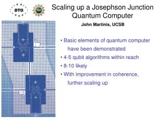
Scaling up a Josephson Junction Quantum Computer. John Martinis, UCSB. Basic elements of quantum computer have been demonstrated 4-5 qubit algorithms within reach 8-10 likely With improvement in coherence, further scaling up.

E N D
Scaling up a Josephson JunctionQuantum Computer John Martinis, UCSB • Basic elements of quantum computer • have been demonstrated • 4-5 qubit algorithms within reach • 8-10 likely • With improvement in coherence, • further scaling up
Quantized Voltages and Currentsof Microfabricated Circuit Qubit control port readout port 100mm (old NIST design) control port Josephson Junction forms non-linear LC resonator
U(d) E2 Josephson-Junction Qubit (1) State Preparation Wait t > 1/g10for decay to |0> E1 • |1> E0 • |0> dIdc(t) (2) Qubit logic with current bias I = Idc + dIdc(t) + Imwc(t)cosw10t+ Imws(t)sinw10t I mwc I mws (3) State Measurement: DU(Idc+dIp) Fast single shot – high fidelity 3 ns pulse • |1> : tunnel • |0> : no tunnel
X Y Imw Z Ip Reset Compute Meas.Readout time If Repeat 1000x Probability 0,1 Is 1 0 Vs Is Vs If Sequencer & Timer 300K V source ~10ppm noise ExperimentalApparatus rf filters fiber optics V source Ip ~10ppm noise Z, measure Imw X, Y I-Q switch mwaves 20dB 20dB ~5 ns pulses 4K 20mK mw filters 20dB 10ns 3ns 30dB
x/2 x/2 Ramsey time y x/2 x/2 Echo time x lifetime time Qubit Characterization Rabi Meas. time 1 T1 ~400ns 0 P1 T~100ns 1 t~350ns 0 0 100 200 300 400 500 600 time [ns]
|1> |0> Single Qubit Gate Errors: Measurement Errors nothing or -pulse Iw 7.22 GHz measure Iz Tunneling Prob. 8 ns 3 ns Spectroscopy thy: 96.6% exp: 85.0% TLS leakage Imeas / Ic measurement 6.75 GHz Error Budget thy: 96.6% exp: 89.5% • |1> (misidentified as |0>) • 4.5% splitting at 7GHz • 3-5% other splittings • 1% T1 during measurement • |0> (misidentified as |1>) • 3.4% stray tunneling
Single-Qubit Gate Errors: Limited by T1 X X measure Iw separation Iz P1 [%] 8 ns 8 ns pulse non-linearity T1 decay Vary the time between pi pulses to separate gate fidelity from decoherence due to T1 decay. 4% error at separation 11 ns 3.4% stray tunneling pulse separation [ns] double - error: 4% single-qubit gate fidelity: 98% (limited by T1) Direct measure of probability Checks on measurement & p-gates
Coupled Qubits Straightforward to implement: simple coupling tunable fast readout simultaneous measurement Cc C Cc On Resonance: 11 01 10 00
p t real imag S 11 01 10 Entangling 2-Qubit Gate (Universal) p 00 100 80 |00> 60 Probability of |01>, |10>, or |11> [%] Entanglement of Formation 0.2635 ebit 40 20 t [ns] 0 0 50 100 150 200 250 300 350 400 450 500
Process Tomography of 2-Qubit Gate Re [c] Im [c] Fidelity: Tr(cthycexp) = 0.427 DATA T1 = 450ns CM = 8% CuW= 5% vis = 85% g/π = 20MHz SIM
On-Off Coupling to TLS Memory • Strong interaction with TLS (S = 40MHz) • Long-lived TLS is quantum memory “on” excite qubit off-resonance Frequency • On-Off coupling with change in bias z-pulse into resonance “off” Tswap ~ 12ns Bias X interact with TLS measure P1 8% time [ns] off TLS on 16 ns time time [s] T1,TLS ~ 1.2s X swap hold swap P1 off TLS on 16 ns 12 ns time 12 ns time [s]
Quantum Memory with Process Tomography init store mem load TLS 16 ns 16ns 12 ns 12 ns 1 2 3 Process tomography: identity operation dominates process Fidelity: Tr(thymeas) = 79% 1 – Initialize Create states over the entire Bloch sphere. 2 – Store Swap state into TLS. Qubit now in ground state. 3 – Load After holding for 16ns, swap again to retrieve state from TLS.
Summary and Future Prospects • Demonstrated basic qubit operations with fidelity • Initialize, gate operations, simultaneous measurement • 10 to 50 logic operations Tomography conclusively demonstrates entanglement • Decoherence mechanism understood • Optimize dielectrics, expect future improvements • Working on Bell violation, advanced CNOT gates (+ tunable) • Simulating 4-5 qubit algorithms • Scale-up infrastructure designed (“brute force” to ~100 qubits) Very optimistic about 4 -10 qubit quantum computer
detuning (both pulses) X measure Iw Iz 8 ns 8 ns Single-Qubit Gate Errors: Tomography Check experiment Goal: Measure fidelity of pi-pulse (longest single-qubit gate) separately from measurement errors. Idea: Two pi-pulses bring state back to |0>, where the only measurement error is stray tunneling. Remaining error is due to pi-pulses only. Tomography Check: On resonance, phase of second pulse has no effect, as expected for pi-pulses. detuning [MHz] P1 phase [/] theory P1
Xp |2> Errors from Fast Pulses t (FWHM) Measure Two State Errors Zoom in on 2-state errors for many pulse lengths w21 w10 8ns pulse power 4ns frequency w21 w10 Gaussian pulses: Minimum width in time and frequency
Xp Xp p - p Pulses Give Low Background & Error Filtering High Power Spectroscopy Qubit Two Photon |2> Error tdelay Measure |2> State 200MHz 5 ns 4P2-error Ramsey Fringe Filtering of |2> state Delay time tdelay[ns]
Error vs. Gaussian Pulse Width S-curve 10-4 p-p FT theory Spectrum analyzer Quantum simulation