Download
1 / 12
160 likes | 508 Vues
Example 10.6 Calculating Power in Parallel Loads. Load 1 absorbs an average power of 8 kW at a leading power factor of 0.8. Load 2 absorbs 20 kVA at a lagging power factor of 0.6. Determine the power factor of the two loads in parallel. The total complex power absorbed by the two loads is.

E N D
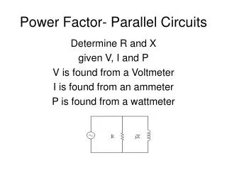
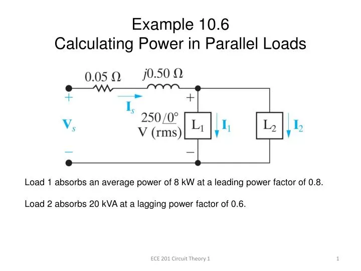
Example 10.6Calculating Power in Parallel Loads Load 1 absorbs an average power of 8 kW at a leading power factor of 0.8. Load 2 absorbs 20 kVA at a lagging power factor of 0.6. ECE 201 Circuit Theory 1
Determine the power factor of the two loads in parallel. The total complex power absorbed by the two loads is ECE 201 Circuit Theory 1
Power Triangle for Load 1 8 kW at a leading power factor of 0.8. cos-1(0.8) leading = -36.87° S1 = 8,000 –j6,000 VA ECE 201 Circuit Theory 1
Power Triangle for Load 2 20 kVA at a lagging power factor of 0.6. cos-1(0.6) lagging = 53.13° S2 = 12,000 +j16,000 VA ECE 201 Circuit Theory 1
S = S1 + S2 = 8,000 – j6,000 = 12,000 +j16,000 S = 20,000 +j10,000 VA The resulting Power Triangle ECE 201 Circuit Theory 1
The power factor of the two loads in parallel is cos(26.57°) = 0.8944 lagging (net reactive power is positive) ECE 201 Circuit Theory 1
Determine the apparent power required to supply the loads, the magnitude of the current IS, and the average power loss in the transmission line. The apparent power which must be supplied to these loads is 22.36 kVA as shown in the power triangle below. ECE 201 Circuit Theory 1
The magnitude of the current that supplies the required 22.36 kVA is The average power lost in the line is due to the current flowing through the line resistance. Note: the total power supplied is equal to 20,400 W, even though the loads require only 20,000 W. ECE 201 Circuit Theory 1
Given that the frequency of the source is 60 Hz, compute the value of capacitor that would correct the power factor to 1 if placed in parallel with the two loads. As seen from the power triangle, the capacitor would have to supply 10 kVAR of magnetizing reactive power. ECE 201 Circuit Theory 1
Calculation of the capacitance from the required reactance ECE 201 Circuit Theory 1
Look at the resulting power triangle • is the sum of the power triangles for loads 1 and 2. • (b) is the power triangle for the 424.4 µF capacitor at 60 Hz. • (c) is the “corrected” power triangle (for a power factor equal to 1). ECE 201 Circuit Theory 1
Once the power factor has been corrected, The total power supplied is now 20,000 + 320 = 20,320 W The line loss has been reduced by correcting the power factor. ECE 201 Circuit Theory 1