Download
1 / 19
190 likes | 264 Vues
10-th INTERNATIONAL CONFERENCE ON INSTRUMENTATION FOR COLLIDING BEAM PHYSICS Novosibirsk, Russia , February 28 - March 5, 2008. March 5, 2008. The CMD-3 Data Acquisition and Control System. A.Ruban*, A.Aulchenko, K.Kakhuta, A.Kozyrev, A.Selivanov, V.Titov, Yu.Yudin BINP, Novosibirsk.

E N D
10-th INTERNATIONAL CONFERENCEON INSTRUMENTATION FOR COLLIDING BEAM PHYSICSNovosibirsk, Russia, February 28 - March 5, 2008 March 5, 2008 • The CMD-3 Data Acquisition and Control System. A.Ruban*,A.Aulchenko, K.Kakhuta, A.Kozyrev, A.Selivanov, V.Titov, Yu.Yudin BINP, Novosibirsk.
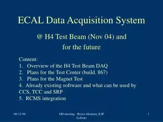
The CMD-3 Data Acquisition and Control System. VEPP-2000 Collider Layout March 5, 2008 • Historical Siberian Snake Round Beams • 2E max = 1.4 GeV 2 GeV • L(1.4 GeV) = 31030sm-2s-11031sm-2s-1 • L(2 GeV)=1032sm-2s-1
The CMD-3 Data Acquisition and Control System. CMD – 3 Subsystem Layout March 5, 2008 1 – Vacuum Pipe 2 – Drift Chamber 3 – BGO Endcap Calorimeter 4 – Z–Chamber 5 – Superconducting Solenoid CMD-3 6 – LXe Calorimeter 7 – CsI Calorimeter 8 – Yoke 9 – Superconducting magnet lenses Mu-System and TOF not showed
The CMD-3 Data Acquisition and Control System. General Requirements to CMD-3 DAQ March 5, 2008 • Number of Channels • DC – 1260 Wires Time, ChargeX2 • ZC – 48 Sectors Time, Charge • - 512 Stripes Charge • BGO – 680 Crystals Charge • CsI – 1152 Crystals Charge • LXe – 264 Towers Time, Charge • - 2112 Stripes Charge • Mu – 48 Counters TimeX2, ChargeX2 • TOF - 16 Counters TimeX2, ChargeX2 • FLT – 400 Chanels Words • Total up to 10k channels
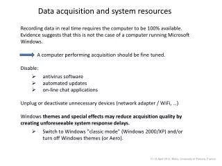
The CMD-3 Data Acquisition and Control System. General Requirements to CMD-3 DAQ March 5, 2008 • Time • Average Speed – 1k Evtps • Dead Time – less then 5% • Common Stop Jitter – less then 20ps • Reliability • End-to-End testability • On-Line Data Check • DAQ Error Rate - less then 0.1% • Density • Low EMI • Low Power • Low-cost • Legacy Interface if possible
The CMD-3 Data Acquisition and Control System. The way we choose March 5, 2008 • Serial Bus rather then Parallel • Point-to-point media connection • Low signal strength differential media • System Clock locked to Bunch Crossing • Data is transmitted along with A/D conversion • No Event buffers in Digitizing Modules • No EMI when Event search in progress • Low EMI allow to have Preamps and A/D converter in single-board solution • Minimize Power consumption to increase channel density • Commercially available components only • CAMAC compatible if possible
The CMD-3 Data Acquisition and Control System. CMD-3 Data Acquisition Electronics Layout March 5, 2008 • Trigger Data Pipeline Synchronization • Event Queue and Time Control • Data Collection • Status Control and Check • Calibration
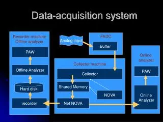
The CMD-3 Data Acquisition and Control System. Data Flow March 5, 2008 • “DAQ Synchro” generates a message with StartBite, Command Code and Event Number • “Data Delivery” distribute it simultaneously to all “Digitizer” modules and Level-1 Trigger modules • All “Digitizers” return Data of current Event • “Data Delivery” collects the Data, and then transmit it to Event Builder
The CMD-3 Data Acquisition and Control System. CMD-3 Link intro March 5, 2008 • All messages are transported by specially designed media “CMD-3 DAQ Link” • DAQ System Bus includes ~400 Links • This Bus is a serial backplane with Point-to-Point connection and root hierarchy
The CMD-3 Data Acquisition and Control System. CMD-3 Link Stack March 5, 2008 • Bidirectional Data Line, No preamble due to dedicated Clock Line • Coincidence of StartBit Level and Clock Line Transition is Common Stop • Messages are transmitted to “Data Delivery” Modules through Links • Answer from Digitizer contains Event Number, Board ID, Status Word • Command Code is covered with parity, Data is covered with CRC
The CMD-3 Data Acquisition and Control System. CMD-3 Link Phy March 5, 2008
The CMD-3 Data Acquisition and Control System. Event’s Queue and Time Control March 5, 2008 • “Event Manager” accepts Requests, and Builds Event’s Queue • “Event Controller” serves Queue one-by-one and convert it to Stream of DAQ Messages • Trigger’s Event are serviced immediately or skipped other are settled in queue • Messages are transmitted to “Data Delivery” Modules through Links
The CMD-3 Data Acquisition and Control System. Data Collection March 5, 2008 • “Data Delivery” distributes the Message to Digitizers • “Data Delivery” receives Data and accumulates them in RAM • Ethernet 100 Controller transmits Data from RAM through Ethernet Switch to Event Builder • Ethernet Switch solves a collision problem
The CMD-3 Data Acquisition and Control System. Inside Digitizer March 5, 2008 • When Message reaches the Digitizer associated Command List is activated and executed • Any Digitizer resource can be accessed for read or write as preprogrammed in Message specific Command List. • “Redirector” feature includes Command List’s RAM and glue Logic.
The CMD-3 Data Acquisition and Control System. Trigger Data Pipeline Synchronization March 5, 2008 • Each Triggering Module has “Cavity Frequency Restorer”, based on FPGA’s PLL and binary counter. Relative phase of counter is settled by leading edge of Common Stop. This insures that all “Cavity Frequency Restorers” in DAQ has same phase. Introducing Link-to-Link delay we can control and align pipeline latency of different Triggering Module. Calibration • When Calibration Event generated, Links to Calibrating Modules are started immediately while some delay introduced for all “Normal” Links. Pushing this Link-to-Link delay we can control Calibrating process.
The CMD-3 Data Acquisition and Control System. CMD-3 “Standard Design” for board’s compatibility. March 5, 2008 • To obtain compatibility of different digitizers in DAQ single style is required. • Specific “Standard Design” was developed. • It includes all function required for digitizer to work in DAQ. • It supports full independent access from any interface. • Supports modular approach for Board specific Controllers • Code is written in Altera HDL
The CMD-3 Data Acquisition and Control System. Module for synChronization of System MChS March 5, 2008 • Logic functions which are implemented and tested with Prototype Module. • Hardware features to be added for specified jitter performance. • “Standard Design” • Automatic Status Control.
The CMD-3 Data Acquisition and Control System. CMD-3 DAQ Status March 5, 2008 • “DAQ Synchro”: • Prototype module with 6 Down_Links are under tests since April 07 • Full size, full feature Module will come soon. • “Data Delivery”: • Two serial modules are under tests since November 07 • “Digitizers”: • 5 types of Digitizers and TrackFinder are under tests now • Test modules Down_Link and Up_Link are in use since September 06 • Error Rate in 1 Link at testbench – less than 10-8 • Error Rate in full System – less than 10-4 • All Speed requirements are achieved
The CMD-3 Data Acquisition and Control System. End March 5, 2008 • Thank You for attention