Download
1 / 10
110 likes | 248 Vues
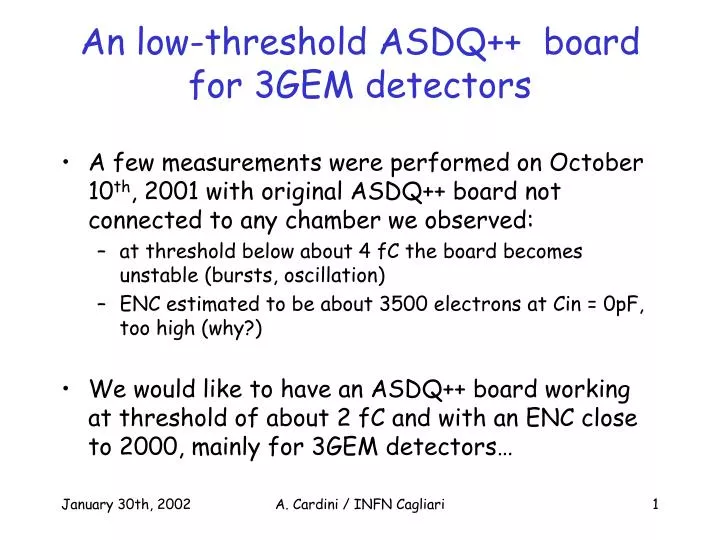
An low-threshold ASDQ++ board for 3GEM detectors. A few measurements were performed on October 10 th , 2001 with original ASDQ++ board not connected to any chamber we observed: at threshold below about 4 fC the board becomes unstable (bursts, oscillation)

E N D
An low-threshold ASDQ++ board for 3GEM detectors • A few measurements were performed on October 10th, 2001 with original ASDQ++ board not connected to any chamber we observed: • at threshold below about 4 fC the board becomes unstable (bursts, oscillation) • ENC estimated to be about 3500 electrons at Cin = 0pF, too high (why?) • We would like to have an ASDQ++ board working at threshold of about 2 fC and with an ENC close to 2000, mainly for 3GEM detectors… A. Cardini / INFN Cagliari
The ASDQ COT board • Mitch Newcomer says that the ASDQ COT board “is a good example of a reasonable 2 fC design”. outputs inputs A. Cardini / INFN Cagliari
The ASDQ COT board • These are a few design rules from Mitch: • Common ground plane splits to prevent current from traveling under the chip or near the input traces • Input traces are wired in pairs as much as possible. The space between differential pairs should not be too small because the increase in intrinsic noise due to capacitance between inputs is 2 times larger than an equivalent capacitance to ground. A ground between pairs could be used to improve crosstalk. • At output a special bus is used to contact the output cable shield. This bus is attached to board ground through low value (a few ohms) resistors. • Detector reference is connected in several places at the front of the board. Power reference is connected near the back. • … but also: • input on one side and output on the opposite side of the board! A. Cardini / INFN Cagliari
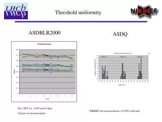
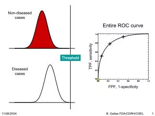
Measurements on the ASDQ COT board s-curve at various thresholds and the calibration curve at Cin = 0 pF ENC = 2350 electrons at Cin = 0 pF A. Cardini / INFN Cagliari
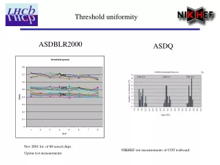
Measurements on the ASDQ COT board ENC vs. Cin noise counts vs threshold for Cin = 0 pF Very stable operation down to 2 fC No bursts – no oscillations, even at Cin = 15 pF A. Cardini / INFN Cagliari
A new ASDQ++ layout • Mechanically compatible in input with existing Anatoli ASDQ++ board • Electrically equivalent to ASDQ++ board • We tried to follow Mitch directives, even if we cannot have inputs on one side and outputs on the other! • Board will be submitted next week for production, hope to have some results at mid-march. A. Cardini / INFN Cagliari
A new ASDQ++ layout – GND plane output/power connector inputs inputs A. Cardini / INFN Cagliari
A new ASDQ++ layout – PWR plane inputs inputs A. Cardini / INFN Cagliari
A new ASDQ++ layout – top plane inputs inputs output/power connector A. Cardini / INFN Cagliari
A new ASDQ++ layout – bot plane inputs inputs A. Cardini / INFN Cagliari