Download
1 / 67
670 likes | 782 Vues
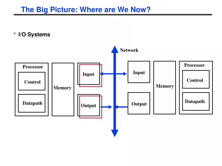
Control. Control. Datapath. Datapath. The Big Picture: Where are We Now?. I/O Systems. Network. Processor. Processor. Input. Input. Memory. Memory. Output. Output. interrupts. Processor. Cache. Memory - I/O Bus. Main Memory. I/O Controller. I/O Controller. I/O Controller.

E N D
Control Control Datapath Datapath The Big Picture: Where are We Now? • I/O Systems Network Processor Processor Input Input Memory Memory Output Output
interrupts Processor Cache Memory - I/O Bus Main Memory I/O Controller I/O Controller I/O Controller Graphics Disk Disk Network I/O System Design Issues • Performance • Expandability • Resilience in the face of failure
I/O Device Examples Device Behavior Partner Data Rate (KB/sec) Keyboard Input Human 0.01 Mouse Input Human 0.02 Line Printer Output Human 1.00 Floppy disk Storage Machine 50.00 Laser Printer Output Human 100.00 Optical Disk Storage Machine 500.00 Magnetic Disk Storage Machine 5,000.00 Network-LAN Input or Output Machine 20 – 1,000.00 Graphics Display Output Human 30,000.00
I/O System Performance • I/O System performance depends on many aspects of the system (“limited by weakest link in the chain”): • The CPU • The memory system: • Internal and external caches • Main Memory • The underlying interconnection (buses) • The I/O controller • The I/O device • The speed of the I/O software (Operating System) • The efficiency of the software’s use of the I/O devices • Two common performance metrics: • Throughput: I/O bandwidth • Response time: Latency
Simple Producer-Server Model • Throughput: • The number of tasks completed by the server in unit time • In order to get the highest possible throughput: • The server should never be idle • The queue should never be empty • Response time: • Begins when a task is placed in the queue • Ends when it is completed by the server • In order to minimize the response time: • The queue should be empty • The server will be idle Producer Queue Server
Throughput versus Respond Time Response Time (ms) 300 200 100 20% 40% 60% 80% 100% Percentage of maximum throughput
Throughput Enhancement Server • In general throughput can be improved by: • Throwing more hardware at the problem • reduces load-related latency • Response time is much harder to reduce: • Ultimately it is limited by the speed of light (but we’re far from it) Queue Producer Queue Server
I/O Benchmarks for Magnetic Disks • Supercomputer application: • Large-scale scientific problems => large files • One large read and many small writes to snapshot computation • Data Rate: MB/second between memory and disk • Transaction processing: • Examples: Airline reservations systems and bank ATMs • Small changes to large sahred software • I/O Rate: No. disk accesses / second given upper limit for latency • File system: • Measurements of UNIX file systems in an engineering environment: • 80% of accesses are to files less than 10 KB • 90% of all file accesses are to data with sequential addresses on the disk • 67% of the accesses are reads, 27% writes, 6% read-write • I/O Rate & Latency: No. disk accesses /second and response time
Magnetic Disk • Purpose: • Long term, nonvolatile storage • Large, inexpensive, and slow • Lowest level in the memory hierarchy • Two major types: • Floppy disk • Hard disk • Both types of disks: • Rely on a rotating platter coated with a magnetic surface • Use a moveable read/write head to access the disk • Advantages of hard disks over floppy disks: • Platters are more rigid ( metal or glass) so they can be larger • Higher density because it can be controlled more precisely • Higher data rate because it spins faster • Can incorporate more than one platter Registers Cache Memory Disk
Organization of a Hard Magnetic Disk • Typical numbers (depending on the disk size): • 500 to 2,000 tracks per surface • 32 to 128 sectors per track • A sector is the smallest unit that can be read or written • Traditionally all tracks have the same number of sectors: • Constant bit density: record more sectors on the outer tracks • Recently relaxed: constant bit size, speed varies with track location Platters Track Sector
Magnetic Disk Characteristic Track • Cylinder: all the tacks under the head at a given point on all surface • Read/write data is a three-stage process: • Seek time: position the arm over the proper track • Rotational latency: wait for the desired sectorto rotate under the read/write head • Transfer time: transfer a block of bits (sector)under the read-write head • Average seek time as reported by the industry: • Typically in the range of 8 ms to 12 ms • (Sum of the time for all possible seek) / (total # of possible seeks) • Due to locality of disk reference, actual average seek time may: • Only be 25% to 33% of the advertised number Sector Cylinder Platter Head
Typical Numbers of a Magnetic Disk Track Sector • Rotational Latency: • Most disks rotate at 3,600 to 7200 RPM • Approximately 16 ms to 8 ms per revolution, respectively • An average latency to the desiredinformation is halfway around the disk: 8 ms at 3600 RPM, 4 ms at 7200 RPM • Transfer Time is a function of : • Transfer size (usually a sector): 1 KB / sector • Rotation speed: 3600 RPM to 7200 RPM • Recording density: bits per inch on a track • Diameter typical diameter ranges from 2.5 to 5.25 in • Typical values: 2 to 12 MB per second Cylinder Platter Head
Disk I/O Performance Request Rate • Disk Access Time = Seek time + Rotational Latency + Transfer time + Controller Time + Queueing Delay • Estimating Queue Length: • Utilization = U = Request Rate / Service Rate • Mean Queue Length = U / (1 - U) • As Request Rate -> Service Rate • Mean Queue Length -> Infinity Service Rate Disk Controller Disk Queue Processor Disk Controller Disk Queue
Example • 512 byte sector, rotate at 5400 RPM, advertised seeks is 12 ms, transfer rate is 4 BM/sec, controller overhead is 1 ms, queue idle so no service time • Disk Access Time = Seek time + Rotational Latency + Transfer time + Controller Time + Queueing Delay • Disk Access Time = 12 ms + 0.5 / 5400 RPM + 0.5 KB / 4 MB/s + 1 ms + 0 • Disk Access Time = 12 ms + 0.5 / 90 RPS + 0.125 / 1024 s + 1 ms + 0 • Disk Access Time = 12 ms + 5.5 ms + 0.1 ms + 1 ms + 0 ms • Disk Access Time = 18.6 ms • If real seeks are 1/3 advertised seeks, then its 10.6 ms, with rotation delay at 50% of the time!
Magnetic Disk Examples Characteristics IBM 3090 IBM UltraStar Integral 1820 Disk diameter (inches) 10.88 3.50 1.80 Formatted data capacity (MB) 22,700 4,300 21 MTTF (hours) 50,000 1,000,000 100,000 Number of arms/box 12 1 1 Rotation speed (RPM) 3,600 7,200 3,800 Transfer rate (MB/sec) 4.2 9-12 1.9 Power/box (watts) 2,900 13 2 MB/watt 8 102 10.5 Volume (cubic feet) 97 0.13 0.02 MB/cubic feet 234 33000 1050
Reliability and Availability • Two terms that are often confused: • Reliability: Is anything broken? • Availability: Is the system still available to the user? • Availability can be improved by adding hardware: • Example: adding ECC on memory • Reliability can only be improved by: • Bettering environmental conditions • Building more reliable components • Building with fewer components • Improve availability may come at the cost of lower reliability
Disk Arrays • A new organization of disk storage: • Arrays of small and inexpensive disks • Increase potential throughput by having many disk drives: • Data is spread over multiple disk • Multiple accesses are made to several disks • Reliability is lower than a single disk: • But availability can be improved by adding redundant disks (RAID):Lost information can be reconstructed from redundant information • MTTR: mean time to repair is in the order of hours • MTTF: mean time to failure of disks is tens of years
Processor Input Control Memory Datapath Output A Bus is: • shared communication link • single set of wires used to connect multiple subsystems • A Bus is also a fundamental tool for composing large, complex systems • systematic means of abstraction
BUSES Connecting I/O Devices to Processor and Memory
Example: Pentium System Organization Processor/Memory Bus PCI Bus I/O Busses
Memory Processor Advantages of Buses • Versatility: • New devices can be added easily • Peripherals can be moved between computersystems that use the same bus standard • Low Cost: • A single set of wires is shared in multiple ways • Manage complexity by partitioning the design I/O Device I/O Device I/O Device
Memory Processor Disadvantage of Buses • It creates a communication bottleneck • The bandwidth of that bus can limit the maximum I/O throughput • The maximum bus speed is largely limited by: • The length of the bus • The number of devices on the bus • The need to support a range of devices with: • Widely varying latencies • Widely varying data transfer rates I/O Device I/O Device I/O Device
The General Organization of a Bus • Control lines: • Signal requests and acknowledgments • Indicate what type of information is on the data lines • Data lines carry information between the source and the destination: • Data and Addresses • Complex commands Control Lines Data Lines
Master versus Slave • A bus transaction includes two parts: • Issuing the command (and address) – request • Transferring the data – action • Master is the one who starts the bus transaction by: • issuing the command (and address) • Slave is the one who responds to the address by: • Sending data to the master if the master ask for data • Receiving data from the master if the master wants to send data Master issues command Bus Master Bus Slave Data can go either way
Types of Buses • Processor-Memory Bus (design specific) • Short and high speed • Only need to match the memory system • Maximize memory-to-processor bandwidth • Connects directly to the processor • Optimized for cache block transfers • I/O Bus (industry standard) • Usually is lengthy and slower • Need to match a wide range of I/O devices • Connects to the processor-memory bus or backplane bus • Backplane Bus (standard or proprietary) • Backplane: an interconnection structure within the chassis • Allow processors, memory, and I/O devices to coexist • Cost advantage: one bus for all components
A Computer System with One Bus: Backplane Bus • A single bus (the backplane bus) is used for: • Processor to memory communication • Communication between I/O devices and memory • Advantages: Simple and low cost • Disadvantages: slow and the bus can become a major bottleneck • Example: IBM PC - AT Backplane Bus Processor Memory I/O Devices
A Two-Bus System • I/O buses tap into the processor-memory bus via bus adaptors: • Processor-memory bus: mainly for processor-memory traffic • I/O buses: provide expansion slots for I/O devices • Apple Macintosh-II • NuBus: Processor, memory, and a few selected I/O devices • SCCI Bus: the rest of the I/O devices Processor Memory Bus Processor Memory Bus Adaptor Bus Adaptor Bus Adaptor I/O Bus I/O Bus I/O Bus
Bus Adaptor Bus Adaptor A Three-Bus System • A small number of backplane buses tap into the processor-memory bus • Processor-memory bus is used for processor memory traffic • I/O buses are connected to the backplane bus • Advantage: loading on the processor bus is greatly reduced Processor Memory Bus Processor Memory Bus Adaptor I/O Bus Backplane Bus I/O Bus
What defines a bus? Transaction Protocol Timing and Signaling Specification Bunch of Wires Electrical Specification Physical / Mechanical Characterisics – the connectors
Synchronous and Asynchronous Bus • Synchronous Bus: • Includes a clock in the control lines • A fixed protocol for communication that is relative to the clock • Advantage: involves very little logic and can run very fast • Disadvantages: • Every device on the bus must run at the same clock rate • To avoid clock skew, they cannot be long if they are fast • Asynchronous Bus: • It is not clocked • It can accommodate a wide range of devices • It can be lengthened without worrying about clock skew • It requires a handshaking protocol
Busses so far Bus Master: has ability to control the bus, initiates transaction Bus Slave: module activated by the transaction Bus Communication Protocol: specification of sequence of events and timing requirements in transferring information. Asynchronous Bus Transfers: control lines (req, ack) serve to orchestrate sequencing. Synchronous Bus Transfers: sequence relative to common clock. Master Slave ° ° ° Control Lines Address Lines Data Lines Multibus: 20 address, 16 data, 5 control, 50ns Pause
Bus Transaction • Arbitration • Request • Action
Arbitration: Obtaining Access to the Bus Control: Master initiates requests • One of the most important issues in bus design: • How is the bus reserved by a devices that wishes to use it? • Chaos is avoided by a master-slave arrangement: • Only the bus master can control access to the bus: It initiates and controls all bus requests • A slave responds to read and write requests • The simplest system: • Processor is the only bus master • All bus requests must be controlled by the processor • Major drawback: the processor is involved in every transaction Bus Master Bus Slave Data can go either way
Multiple Potential Bus Masters: the Need for Arbitration • Bus arbitration scheme: • A bus master wanting to use the bus asserts the bus request • A bus master cannot use the bus until its request is granted • A bus master must signal to the arbiter after finish using the bus • Bus arbitration schemes usually try to balance two factors: • Bus priority: the highest priority device should be serviced first • Fairness: Even the lowest priority device should never be completely locked out from the bus • Bus arbitration schemes can be divided into four broad classes: • Daisy chain arbitration: single device with all request lines. • Centralized, parallel arbitration: see next-next slide • Distributed arbitration by self-selection: each device wanting the bus places a code indicating its identity on the bus. • Distributed arbitration by collision detection: Ethernet uses this.
The Daisy Chain Bus Arbitrations Scheme • Advantage: simple • Disadvantages: • Cannot assure fairness: A low-priority device may be locked out indefinitely • The use of the daisy chain grant signal also limits the bus speed Device 1 Highest Priority Device N Lowest Priority Device 2 Grant Grant Grant Release Bus Arbiter Request wired-OR
Centralized Parallel Arbitration • Used in essentially all processor-memory busses and in high-speed I/O busses Device 1 Device N Device 2 Req Grant Bus Arbiter
Simplest bus paradigm • All agents operate syncronously • All can source / sink data at same rate • => simple protocol • just manage the source and target
Simple Synchronous Protocol • Even memory busses are more complex than this • memory (slave) may take time to respond • it need to control data rate BReq BG R/W Address Cmd+Addr Data1 Data2 Data
Typical Synchronous Protocol • Slave indicates when it is prepared for data xfer • Actual transfer goes at bus rate BReq BG R/W Address Cmd+Addr Wait Data1 Data1 Data2 Data
Increasing the Bus Bandwidth • Separate versus multiplexed address and data lines: • Address and data can be transmitted in one bus cycleif separate address and data lines are available • Cost: (a) more bus lines, (b) increased complexity • Data bus width: • By increasing the width of the data bus, transfers of multiple words require fewer bus cycles • Example: SPARCstation 20’s memory bus is 128 bit wide • Cost: more bus lines • Block transfers: • Allow the bus to transfer multiple words in back-to-back bus cycles • Only one address needs to be sent at the beginning • The bus is not released until the last word is transferred • Cost: (a) increased complexity (b) decreased response time for request
Pipelined Bus Protocols Attempt to initiate next address phase during current data phase
Increasing Transaction Rate on Multimaster Bus • Overlapped arbitration • perform arbitration for next transaction during current transaction • Bus parking • master can holds onto bus and performs multiple transactions as long as no other master makes request • Overlapped address / data phases (prev. slide) • requires one of the above techniques • Split-phase (or packet switched) bus • completely separate address and data phases • arbitrate separately for each • address phase yield a tag which is matched with data phase • ”All of the above” in most modern mem busses
1993 MP Server Memory Bus Survey: GTL revolution Bus MBus Summit Challenge XDBus Originator Sun HP SGI Sun Clock Rate (MHz) 40 60 48 66 Address lines 36 48 40 muxed Data lines 64 128 256 144 (parity) Data Sizes (bits) 256 512 1024 512 Clocks/transfer 4 5 4? Peak (MB/s) 320(80) 960 1200 1056 Master Multi Multi Multi Multi Arbitration Central Central Central Central Slots 16 9 10 Busses/system 1 1 1 2 Length 13 inches 12? inches 17 inches
The I/O Bus Problem • Designed to support wide variety of devices • full set not know at design time • Allow data rate match between arbitrary speed deviced • fast processor – slow I/O • slow processor – fast I/O
Asynchronous Handshake Write Transaction • t0 : Master has obtained control and asserts address, direction, data • Waits a specified amount of time for slaves to decode target • t1: Master asserts request line • t2: Slave asserts ack, indicating data received • t3: Master releases req • t4: Slave releases ack Address Data Read Req Ack Master Asserts Address Next Address Master Asserts Data t0 t1 t2 t3 t4 t5
Read Transaction • t0 : Master has obtained control and asserts address, direction, data • Waits a specified amount of time for slaves to decode target\ • t1: Master asserts request line • t2: Slave asserts ack, indicating ready to transmit data • t3: Master releases req, data received • t4: Slave releases ack Address Data Read Req Ack Master Asserts Address Next Address t0 t1 t2 t3 t4 t5
1993 Backplane/IO Bus Survey Bus SBus TurboChannel MicroChannel PCI Originator Sun DEC IBM Intel Clock Rate (MHz) 16-25 12.5-25 async 33 Addressing Virtual Physical Physical Physical Data Sizes (bits) 8,16,32 8,16,24,32 8,16,24,32,64 8,16,24,32,64 Master Multi Single Multi Multi Arbitration Central Central Central Central 32 bit read (MB/s) 33 25 20 33 Peak (MB/s) 89 84 75 111 (222) Max Power (W) 16 26 13 25
High Speed I/O Bus • Examples • graphics • fast networks • Limited number of devices • Data transfer bursts at full rate • DMA transfers important • small controller spools stream of bytes to or from memory • Either side may need to squelch transfer • buffers fill up
PCI Read/Write Transactions • All signals sampled on rising edge • Centralized Parallel Arbitration • overlapped with previous transaction • All transfers are (unlimited) bursts • Address phase starts by asserting FRAME# • Next cycle “initiator” asserts cmd and address • Data transfers happen on when • IRDY# asserted by master when ready to transfer data • TRDY# asserted by target when ready to transfer data • transfer when both asserted on rising edge • FRAME# deasserted when master intends to complete only one more data transfer
PCI Read Transaction – Turn-around cycle on any signal driven by more than one agent