Download
1 / 9
90 likes | 194 Vues
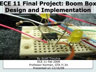
ECE 11 Final Project: Boom Box Design and Implementation. By Scott Trocchia ECE 11 Fall 2008 Professor Korman, GTA Yi Jin Presented on 12/16/08. Definition: break large project (seemingly complicated and daunting task) into its constituents (piece by piece)

E N D
ECE 11 Final Project: Boom Box Design and Implementation By Scott Trocchia ECE 11 Fall 2008 Professor Korman, GTA Yi Jin Presented on 12/16/08
Definition: break large project (seemingly complicated and daunting task) into its constituents (piece by piece) • The following slides will explain the circuit through this concept The Approach: Divide and Conquer
1st order • Inverting design • Establish unity gain • Simple illustration of phasor usage • Eliminates all noise above 10 kHz Stage [1] : Initial Low Pass Filter
Treble channel 2nd order high pass filter • Reason for order? • Unity gain • Frequency range of interest: 5360 Hz to 10 kHz Stage [2a]: Decision to make - Treble or Bass?
Bass channel 2nd order low pass filter • R C, C R • Unity gain, again • Frequency range of interest: 150 Hz to 7360 Hz Stage [2b]: Decision to make - Treble or Bass?
Same for treble and bass channels • C6 and R8 together represent passive low pass filter • Attenuates all frequency <150 Hz • C7 makes sure AC voltage passes to speaker Stage [3]: Output Stage
Concept of voltage ladder (+,- polarity) • Initial resistor highest voltage drop • Personal preference and guess and check • LED resistor? Treble’s Voltage Ladder
Concept of voltage ladder (+,- polarity) • Personal preference, again • LED resistor and why we need it Bass’s Voltage Ladder
Troubleshooting • Parts • Time issue? • Lessons learned and applications Troubleshooting / Problems / Resolutions