Download
1 / 41
410 likes | 524 Vues
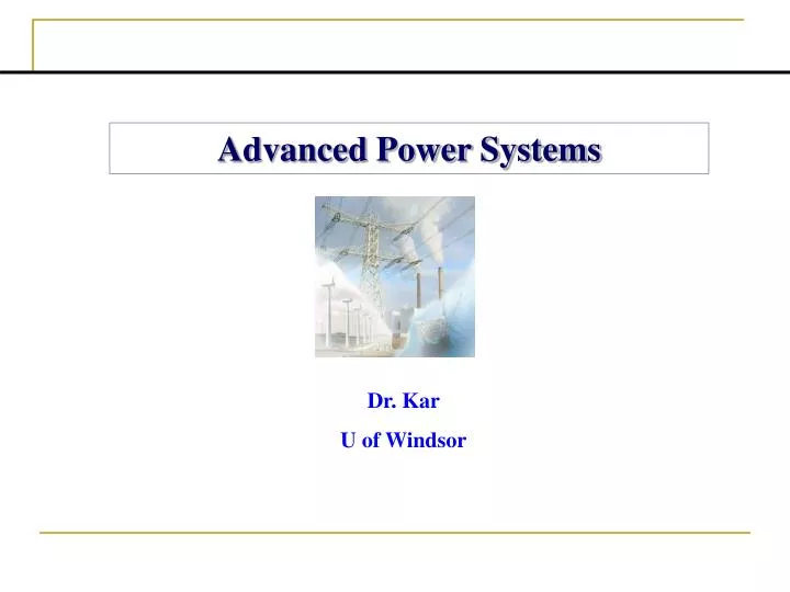
Advanced Power Systems. Dr. Kar U of Windsor. Dr. Kar 271 Essex Hall Email : nkar@uwindsor.ca Office Hour: Thursday, 12:00-2:00 pm http://www.uwindsor.ca/users/n/nkar/88-514.nsf GA: TBA B20 Essex Hall Email: TBA & TBA Office Hour: -----. Course Text Book :

E N D
Advanced Power Systems Dr. Kar U of Windsor
Dr. Kar271 Essex HallEmail: nkar@uwindsor.ca Office Hour: Thursday, 12:00-2:00 pm http://www.uwindsor.ca/users/n/nkar/88-514.nsf GA: TBA B20 Essex Hall Email: TBA & TBA Office Hour: -----
Course Text Book: • Electric Machinery Fundamentals by Stephen J. Chapman, 4th Edition, McGraw-Hill, 2005 • Electric Motor Drives – Modeling, Analysis and Control by R. Krishnan Pren. Hall Inc., NJ, 2001 • Power Electronics – Converters, Applications and Design by N. Mohan, J. Wiley & Son Inc., NJ, 2003 • Power System Stability and Control by P. Kundur, McGraw Hill Inc., 1993 • Research papers Grading Policy: Attendance (5%) Project (20%) Midterm Exam (30%) Final Exam (45%)
Course Content • Working principles, construction, mathematical modeling, operating characteristics and control techniques for synchronous machines • Working principles, construction, mathematical modeling, operating characteristics and control techniques for induction motors • Introduction to power switching devices • Rectifiers and inverters • Variable frequency PWM-VSI drives for induction motors • Control of High Voltage Direct Current (HVDC) systems
Exam Dates • Midterm Exam: • Final Exam:
Term Projects Group 1:Student 1 (---@uwindsor.ca)Student 2 (---@uwindsor.ca)Student 3 (---@uwindsor.ca) Project Title:Group 2:Student 1 (---@uwindsor.ca)Student 2 (---@uwindsor.ca)Student 3 (---@uwindsor.ca)Project Title: Group 3:Student 1 (---@uwindsor.ca)Student 2 (---@uwindsor.ca)Student 3 (---@uwindsor.ca)
Synchronous Machines • Construction • Working principles • Mathematical modeling • Operating characteristics
d-axis • Non-uniform air-gap • N • D»10m • q-axis • S • S • Turbine • N • Hydro (water) • Salient-Pole Synchronous Generator • Most hydraulic turbines have to turn at low speeds (between 50 and 300 r/min) • A large number of poles are required on the rotor Hydrogenerator
Salient-Pole Synchronous Generator • Stator • Salient-pole rotor
Cylindrical-Rotor Synchronous Generator • Stator • Cylindrical rotor
Operation Principle The rotor of the generator is driven by a prime-mover A dc current is flowing in the rotor winding which produces a rotating magnetic field within the machine The rotating magnetic field induces a three-phase voltage in the stator winding of the generator
Electrical Frequency Electrical frequency produced is locked or synchronized to the mechanical speed of rotation of a synchronous generator: where fe = electrical frequency in Hz P = number of poles nm= mechanical speed of the rotor, in r/min
d-axis q-axis Direct & Quadrature Axes Stator winding N Uniform air-gap Stator Rotor winding Rotor S Turbogenerator
PU System Per unit system, a system of dimensionless parameters, is used for computational convenience and for readily comparing the performance of a set of transformers or a set of electrical machines. Where ‘actual quantity’ is a value in volts, amperes, ohms, etc. [VA]base and [V]base are chosen first.
Classical Model of Synchronous Generator • The leakage reactance of the armature coils, Xl • Armature reaction or synchronous reactance, Xs • The resistance of the armature coils, Ra • If saliency is neglected, Xd = Xq = Xs jXl Ra jXs + Ia + Vt 0o E d Equivalent circuit of a cylindrical-rotor synchronous machine
Phasor Diagram q-axis E IaXs d Vt IaXl f IaRa Ia d-axis
The following are the parameters in per unit on machine rating of a 555 MVA, 24 kV, 0.9 p.f., 60 Hz, 3600 RPM generator • Lad=1.66 Laq=1.61 Ll=0.15 Ra=0.003 • When the generator is delivering rated MVA at 0.9 p. f. (lag) and rated terminal voltage, compute the following: • (i) Internal angle δi in electrical degrees • (ii) Per unit values of ed, eq, id, iq, ifd • (iii) Air-gap torque Te in per unit and in Newton-meters
(b) Compute the internal angle δi and field current ifd using the following equivalent circuit
Direct and Quadrature Axes • The direct (d) axis is centered magnetically in the center of the north pole • The quadrature axis (q) axis is 90o ahead of the d-axis • q: angle between the d-axis and the axis of phase a • Machine parameters in abc can then be converted into d/q frame using q • Mathematical equations for synchronous machines can be obtained from the d- and q-axis equivalent circuits • Advantage: machine parameters vary with rotor position w.r.t. stator, q, thus making analysis harder in the abc axis frame. Whereas, in the d/q reference frame, parameters are constant with time or q. • Disadvantage: only balanced systems can be analyzed using d/q-axis system
yq Xl Xfd Ifd Ikd1 Imd + + Rfd pykd1 Rkd1 Xmd pyd - pyfd + vfd Ra Id Xkd1 - - d-axis Imd=-Id+Ifd+Ikd1 Imq=-Iq+Ikq1 Vtd - yd Xl Ikq1 Imq + pykq1 Rkq1 Xmq pyq - Xkq1 q-axis Ra Iq Vtq d- and q-Axis Equivalent Circuits
Small disturbances in a power system • Gradual changes in loads • Manual or automatic changes of excitation • Irregularities in prime-mover input, etc. Importance of steady-state stability • Knowledge of steady-state stability provides valuable information about the dynamic characteristics of different power system components and assists in their design • - Power system planning • - Power system operation • - Post-disturbance analysis
Related Terms • Generator Modelingusing the d- and q-axis equivalent circuits • Transmission System Modelingwith a RL circuit • A Small Disturbance is a disturbance for which the set of equations describing the power system may be linearized for the purpose of analysis • Steady-State Stability is the ability to maintain synchronism when the system is subjected to small disturbances • Loss of synchronism is the usual symptom of loss of stability • Infinite Bus is a system with constant voltage and constant frequency, which is the rest of the power system • Eigen values and eigen vectors are used to identify system steady-state stability condition
The Voltage Equations ……………..(1)
……………..(2) where The Mechanical Equations
Linearized Form of the Machine Model ……………..(3)
Terminal Voltage The d- and q-axis components of the machine terminal voltage can be described by the following equations: ………………………….(4) where, Vt is the machine terminal voltage in per unit. The linearized form of Vtdand Vtqare: ……………………….…(5)
Rearranging the flux equations in a matrix form: ………………...…..(7) where,
Flux Linkage Equations (from the d- and q-axis equivalent circuits) Linearized flux linkage equations:
and thus, ………………………………………...(8)
where, : from (8) : inserting (8) into (7) ………..(9) : system state matrix
Vt Generator It Infinite Bus System to be Studied
Eigen Values: System State Matrix and Eigen Values System State Matrix:
Eigen Values • Eigen values are the roots of the characteristic equation • Number of eigen values is equal to the order of the characteristic equation or number of state variables • Eigen values describe the system response ( ) to any disturbance
Analyzing the Eigen Values of the System State Matrix • Compute the eigen values of the system state matrix, A • The eigen values will give necessary information about the steady-state stability of the system • Stable System: If the real parts of ALL the eigen values are negative Example: • A system with the above eigen values is on the verge of instability
Machine Parameters Salient-pole synchronous generator 3kVA, 220V, 4-pole, 60 Hz and 1800 r/min