Download
1 / 24
240 likes | 411 Vues
Hip Implant -Thin Film Improved-. Ahmed, Nouman Hirvonen , Saara Lavanti , Kimmo Lehikoinen , Lotta Multaharju , Miikka. Key Issues. What can we do to improve hip implants Structural construction Bone growth enhancement Low friction coating Surface testing and analysis imaging

E N D
Hip Implant -Thin Film Improved- Ahmed, Nouman Hirvonen, Saara Lavanti, Kimmo Lehikoinen, Lotta Multaharju, Miikka
Key Issues • What can we do to improve hip implants • Structural construction • Bone growth enhancement • Low friction coating • Surface testing and analysis imaging • Integrated sensoring system
Improvement areas • Loosening of the stem • Dislocation of the joint • Detached particles from the surfaces • The right time for replacement • Easy replacement • Proper testing
DISADVANTAGES of using this structure • Metallosis • Heavy metal poisoning • Metal sensitivity • Bone deterioration • Tissue damage • Particles entering the blood stream and in soft tissues
Risk of displacement • A small head size increase the risk of dislocation • With a large head the risk of dislocation after same traveled distance is reduced • Cup displacement affects the clearance and can increase the risk of wear which can be reduced by maintaining the fluid film interface
Possible Solutions • Hydrophilic coating to facilitate the state of fluid film lubrication • Bearings are fully separated and the load fully supported by the lubricant films • Different taper (attachment) options as requirement for better fit and usability
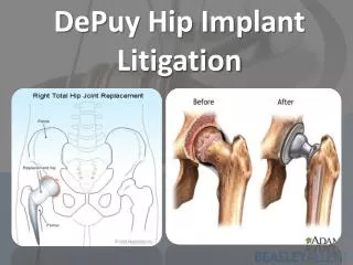
Fixed hip implant with skeleton Old Patients Young Patients Due to continuous bone growth cement can crack off Introduction of cup with porous exterior Porous exterior allows bone to grow in and secure the implant in place • Top of femur is sawn off and replace with artificial new head • Hip bone is shaved down to accommodate man made socket • Bone cement use for attachment
Bone growth enhancement • Implant stem and cup attachment to the bone • Uncemented stems for good quality bone • Cemented devices for poor quality bone (risk of fracture during stem insertion) • Uncemented stems can cause pain during the first year after, as the bone adapts to the device • Porosity and surface coatings can stimulate bone growth and bond to the implant
Bone growth enhancement Acetabular Cup Femoral Component Fits to the femur: anatomic medullary locking Porous coating promote bone ingrowth • Modular cup • The shell is made of metal • The outside has a porous coating http://machinedesign.com/archive/high-performance-hips http://www.zimmer.com/fi-FI/hcp/hip/product/zimmer-mmc-cup.jspx
Bonegrowthenhancement Porous coatings • Titanium plasma spray coating • encourage bone on-growth and in-growth • 34 % porosity • Titanium sintered metal beads • stability and long-term fixation • 35 % porosity • Direct metal laser sintering • 70 % porosity http://www.exac.com/products/hip/resource-library/titanium-plasma-spray http://www.businesswire.com/news/home/20131010005166/en/Initiative Combines-Industrial-3D-Printing-Free-Medical-Implant
Bone growth enhancement • Bone growth can be more enhanced with coatings • Calcium phosphate ceramics coatings on orthopedic implants • Stimulate osseous apposition to the implant surface • Hydroxyapatite HA, “bone mineral” • Increased of the mechanical fixation and bone ongrowth • Plasma-spray • Electrochemical-assisted deposition • Porous AND bone growth enhancing coating → shorter healing time
Coatings against wear and friction • Overall image of the case • Two different coating methods to the top side of the hip implant • DLC and ceramic thin film
Coatings against wear and friction • Diamond-like carbon (DLC) coating deposited using saddle field source deposition system • Deposition directly onto austenitic stainless stell • Biocompatibily accepted • Significantly lower level of wear
Coatings against wear and friction • Ceramic thin films, many different alternatives like TiN, ZrN, NbN, VN and HfN • Usually several layers and these at top • Used for their features of high hardness, electrochemical immunity and biocompatibility • Deposited using reactive magneto sputtering
Coatings against wear and friction • Using a lubricant in the hip joint increases its time-in-use • This is done by rendering the surface more hydrophilic • That way lubricant is more efficient and the friction drops down
Methods of examining the film • SEM to investigate surface structure and wear patterns • Optical white light interferometry to study the surface roughness • Optical microscopy
Methods of examining the film Example of optical interferometry data (Haubold et al., 2010)
Methods of examining the film • Electrochemical investigation to determine implant corrosion, e.g. electrochemical impedance spectroscopy • Energy dispersive X-ray spectroscopy to determine the chemical composition
Methods of examining the film • Hardness testing • Friction testing Example of friction testing equipment (Taposh et al., 2014)
MEMS acoustic emission(AE) transducer • Capacitance change as transduction principle • Integration of high- and low-frequency • Better response & sensitivity (than piezoelectric) • Well defined waveform signature • Source location identification, with an array • Optimized geometry for certain frequencies
Microfabrication of the AE MEMS • Thinfilmlayers • Silicon oxide (2 layers) • Silicon nitride (1+1 layer) • Doped polysiliconelectrode (fixed) • Sacrificial SiO2 • Anchor/platingbasemetal • Electroplatednickel • Gold coating (contactivity+corrosionresistance) • Metallayer is patterned to form a spring and masssystem • The sacrificiallayer is etchedunder the metallayer • Individualelementsaremounted in ceramicpackagewithepoxy H. Saboonchi , D. Ozevin. MEMS acoustic emission transducers designed with high aspect ratio geometry. Smart Mater. Struct. 22 (2013) 095006 (14pp). DOI:10.1088/0964-1726/22/9/095006
Measuring of acoustic emissions • Parameters • Ringdown count • Event ”length” • Peak amplitude • Can detect the growth of subsurface cracks N. Tandon & A. Choudhury. A review of vibration and acoustic measurement methods for the detection of defects in rolling element bearings Original Research Article Tribology International. Volume 32, Issue 8, August 1999, Pages 469-480.
Thank you! Any questions?