Download
1 / 5
50 likes | 162 Vues
RF Specification discussion. MICE RF workshop 16 th April 2012. High Power RF system.

E N D
RF Specification discussion MICE RF workshop 16th April 2012
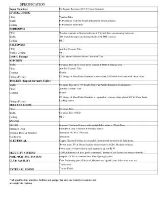
High Power RF system • High voltage power supplies for these amplifiers have been designed that will allow operation at 1 Hz and 1 ms RF pulse length. The amplifier system will be able to produce a maximum of 2 MW of RF power. This will be split between two cavities; however losses in the coax transmission system are expected to reduce the available power by up to ~10 % into each cavity coupler. • The amplifier tubes will typically have a lifetime of at least 15000 hours, performance will degrade within that period which means power levels will decline. The MICE experiment is expected to run for approximately 3 years at a low duty cycle; therefore we expect that one set of tubes will be enough for the experiment. The minimum gradient useful for physics operation is 50% of the initial gradient. • An accelerating gradient of up to 8 MV/m is possible for each cavity in the cooling channel, this equates to 21.4MV on crest acceleration, with each cavity powered by 1 MW of RF power. • 6 1/8 inch and 4 1/16 inch transmission lines will be used. The safe RF working level for these coax systems is 1550 kW and 700 kW respectively (in air). RF pulse shaping will be used to reduce reflected power during cavity filling so that the peak break down voltage level is not exceeded. The coax system will be pressurised with 1.5 Bar of nitrogen to provide an additional voltage breakdown overhead of 10%
Cavity control • A cavity phase angle of ~ 124 degrees will be fixed between cavities driven by a single amplifier system. This will allow muon acceleration to take place between 140 to 240 MeV/c with 98 % efficiency • The field in the MICE cavities will be controlled to ~0.5 Degrees and 1 %. • In order for the gradient loop to function the peak RF power delivered to the cavities will have to be 15-20% lower than the maximum available from the amplifier chain. This will reduce the cavity gradient. • The control of absolute phase with respect to external time is not needed, since the experiment will measure time events during the each cycle. • The cavities will be deformed to have a centre frequency of 201 MHz and have a tuning range of 230 kHz by using mechanical actuators on the cavity body. This tuning system will be active to remove temperature drifts caused by ambient and RF heating changes • Experiment timing with RF is a issue which is only starting to receive some effort, currently there is no real understanding of what is needed here, need to agree the issues and put some effort on to it
Procurement of components • List of components that are possible to purchase based on this specification for this particular layout • Fall back position for use at higher RF power levels will be to pressurise coax with SF6 – only option