Download
1 / 57
600 likes | 779 Vues
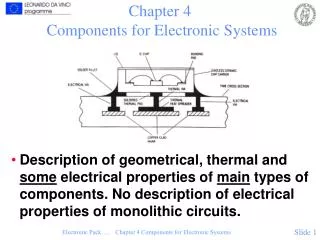
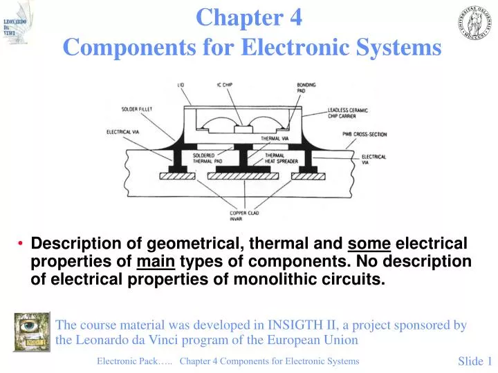
Chapter 4 Components for Electronic Systems. Description of geometrical, thermal and some electrical properties of main types of components. No description of electrical properties of monolithic circuits.

E N D
Chapter 4 Components for Electronic Systems • Description of geometrical, thermal and some electrical properties of main types of components. No description of electrical properties of monolithic circuits. The course material was developed in INSIGTH II, a project sponsored by the Leonardo da Vinci program of the European Union Electronic Pack….. Chapter 4 Components for Electronic Systems
Hole Mounted Resistors • Mature design, fig. 4.1: • Carbon composite (a) • Metal film (b) • Wire wound (c) Electronic Pack….. Chapter 4 Components for Electronic Systems
Surface Mounted Resistors • Fig.4.2.a: Thick film layers on ceramic substrate, rectangular shape Electronic Pack….. Chapter 4 Components for Electronic Systems
Surface Mounted Resistors Fig. 4.2 b): Metal system for termination on SMD resistors. Electronic Pack….. Chapter 4 Components for Electronic Systems
Surface Mounted Resistors Fig. 4.2 c): MELF-resistors have cylindrical body.(MELF is acronym for Metal Electrode Face Bonding) Electronic Pack….. Chapter 4 Components for Electronic Systems
Surface Mounted Resistors • Table 4.1: Properties of SMD resistors Electronic Pack….. Chapter 4 Components for Electronic Systems
Surface Mounted Resistors • Table 4.2: The resistance series E24, 12 and 6 Electronic Pack….. Chapter 4 Components for Electronic Systems
Capacitors • In addition the capacitance, the following properties are important: • Maximum voltage rating • Temperature dependence of the capacitance (temperature coefficient) • Loss tangent (tan δ), see below • Equivalent series resistance • Long term stability and ageing phenomena • High frequency properties • Leakage current • Ability to withstand various production processes (high temperature, etc.) • Price, physical size, etc. Electronic Pack….. Chapter 4 Components for Electronic Systems
Capacitors, continued • Electrical model:C = (eo er • A) /d • Fig. 4.3: Electrical equivalent model for capacitor. If Rp can be neglected the impedance is given by: | Z | = [ Rs2 + (ωL - 1/ ωC)2]1/2Rs = series resistance (Rp neglected),L = inductance Electronic Pack….. Chapter 4 Components for Electronic Systems
Capacitors, continued • Fig. 4.4: The frequency dependence of impedance for multilayer ceramic capacitors (below) and tantalum electrolytic capacitors (top), all having 100 nF capacitance value. Zmin at frequency where:wL = 1/wC Electronic Pack….. Chapter 4 Components for Electronic Systems
Capacitors, continued Fig. 4.5: Frequency dependence of the loss tangent tan d schematically.tan d = R / |Im Z | = [Rp + Rs ( 1+ ( wCRp)2) ] / ( wCRp2 - w L (1+ ( wCRp)2) ] Electronic Pack….. Chapter 4 Components for Electronic Systems
Capacitors, continued • Main types: • Ceramic multilayer • Electrolytic dry, polarized • Electrolytic, wet, polarized • Metallized plastic film • Mica http://en.wikipedia.org/wiki/Capacitors SMD ceramic at top leftSMD tantalum at bottom leftthrough-hole tantalum at top rightthrough-hole electrolytic at bottom right http://en.wikipedia.org/wiki/CapacitorsVarious Capacitors. The large cylinders are high value electrolytic types Electronic Pack….. Chapter 4 Components for Electronic Systems
Capacitors, continued • Multilayer Ceramic Capacitors Fig. 4.7.a: SMD Multilayer Ceramic Capacitor Fig. 4.7.b: Metal system for the end termination of multilayer ceramic capacitors. Electronic Pack….. Chapter 4 Components for Electronic Systems
Multilayer Ceramic Capacitor, continued • Class 1: Low capacitance, good electrical properties, types NP0, N220, N750, COG, etc. • Class 2: High capacitance, poorer electrical behaviour, types X7R, Z5U Fig. 4.8: Relative dielectric constant for ferroelectric ceramic compositions (class 2), as a function of temperature, near the Curie point Electronic Pack….. Chapter 4 Components for Electronic Systems
Multilayer Ceramic Capacitors, continued Fig. 4.9: Properties of dielectrics of the types NP0, X7R and Z5U in SMD ceramic multilayer capacitors. Top: The voltage dependence of capacitance. Middle: Loss tangent as function of temperature.Bottom: The temperature coefficient of the capacitance (Philips). Electronic Pack….. Chapter 4 Components for Electronic Systems
Multilayer Ceramic Capacitors, continued Fig. 4.10: Crack formation because of thermal stress in ceramic capacitors Electronic Pack….. Chapter 4 Components for Electronic Systems
Capacitors, continued • Tantalum, Dry Electrolytic • Very high capacitance, low voltages, low leakage current http://www.nec-tokin.com • Electrolytic Capacitors – why they are polarised: • The capacitance is the oxidised surface of the anode • Reversed polarity will remove the oxide by reduxtion reaction Electronic Pack….. Chapter 4 Components for Electronic Systems
Capacitors, continued • Tantalum, Dry Electrolytic Fig. 4.11 b): Electrical properties of dry tantalum electrolytic capacitors. (Data from Philips) Electronic Pack….. Chapter 4 Components for Electronic Systems
Wet Electrolytic Aluminium Capacitors Fig. 4.12 a): Aluminium electrolytic capacitor for SMD mounting. (From Philips) Electronic Pack….. Chapter 4 Components for Electronic Systems
Wet Electrolytic Aluminium Capacitors Fig. 4.12 b):Aluminium electrolytic capacitor properties (Philips). Top: Temperature dependence of the capacitance, relative to the value at 20 °C. Middle: Temperature dependence of tan d. Bottom: Temperature dependence of impedance at a frequency of 10 kHz. Electronic Pack….. Chapter 4 Components for Electronic Systems
Diodes and Transistors Fig. 4.13: Axial, plastic encapsulated, hole mounted diodes to the left. Centre: A plastic can with metal base for power diodes. It can be hole mounted or surface mounted, depending on how the leads are bent. The base is screwed to the substrate. Right: A higher power diode in a metal can. Screw mounted to the substrate for efficient thermal contact. Electronic Pack….. Chapter 4 Components for Electronic Systems
Diodes and Transistors, continued Fig. 4.14: Various types of hole mounted transistor packages: a) Left: Plastic packages, b) Centre: Low power metal packages c) Right: Metal package for high power transistors. For the high power package, the collector is connected to the metal body. Electronic Pack….. Chapter 4 Components for Electronic Systems
Diodes and Transistors , continued Fig. 4.15: MELF-package for SMD diodes. The standard size is designated SOD-80, with dimensions shown to the right. (MELF: Metal Electrode Face Bonding) Electronic Pack….. Chapter 4 Components for Electronic Systems
Diodes and Transistors, continued Fig. 4.16: SOT-packages for SMD diodes and transistors: The most common, SOT-23 top left, SOT-89 for power transistors in the middle, and SOT-143 with four terminals to the right. The dimensions for SOT-23 are shown bottom left, and a cut-through SOT-89 in the middle. Ceramic SMD transistor packages with terminal placement like for SOT-23 are shown bottom right. Electronic Pack….. Chapter 4 Components for Electronic Systems
IC Packages • Plastic or Ceramic IC Packages? • Plastic: • Not hermetic • Low price in large quantities • High initial cost • Low thermal conductivity • Limited time at high temperature • Thermal mismatch to Si chip and metals • Not suitable for for high frequency circuits • Ceramic: • Hermetic, good reliability • Costly, but OK for prototyping • Good thermal conductivity • Low thermal coefficient of expansion, matches well with Si, mismatch to organic substrates • Gold metallization must be removed • Well defined high frequency properties Electronic Pack….. Chapter 4 Components for Electronic Systems
Packages for Hole Mounted ICs Fig. 4.17:a) DIP (Dual-in-line) IC package. b) Partly cross-sectioned DIP package which shows the silicon chip, bonding wires, lead frame and plastic body. c) The terminal organisation for 4 two-input NOR gates in a 14 pins package. Electronic Pack….. Chapter 4 Components for Electronic Systems
Packages for Hole Mounted ICs, continued Fig. 4.18: Pin grid packages: To the left a cavity up ceramic package, and to the right a plastic moulded package. Electronic Pack….. Chapter 4 Components for Electronic Systems
SMD IC Packages • Small Outline (SO) • Plastic Leaded Chip Carrier (PLCC) • Leadless Chip Carrier (LLCC) • Leaded Ceramic Chip Carrier (LDCC) • Flatpack, mini-flatpack • TapePak • Chip Scale Packages Electronic Pack….. Chapter 4 Components for Electronic Systems
SMD IC Packages, continued Fig. 4.19: Surface mounted SO (Small Outline) IC package. (From Philips) Electronic Pack….. Chapter 4 Components for Electronic Systems
SMD IC Packages, continued Table 4.3: Dimensions for SO- and VSO packages. Centre-to-centre lead distance is normally 50 mils, except for VSO-40 with 30 mils and VSO-56 with 0.75 mm. Electronic Pack….. Chapter 4 Components for Electronic Systems
SMD IC Packages:Plastic Leaded Chip Carrier (PLCC) Fig. 4.20: Plastic leaded chip carrier with (PLCC). They are normally square with an equal number of terminals on all four sides (top). For large DRAMs, the package has terminals on only two sides, also being called SOJ. The bottom figure shows a 1 or 4 Mbit DRAM package. Electronic Pack….. Chapter 4 Components for Electronic Systems
SMD IC Packages:Plastic Leaded Chip Carrier (PLCC) Table 4.4: Dimensions for PLCC packages. Format means the number of terminals on two neighbouring sides. Electronic Pack….. Chapter 4 Components for Electronic Systems
Leadless Chip Carrier (LLCC)Leaded Ceramic Chip Carrier (LDCC) Fig. 4.21 a): The various types of ceramic chip carriers [4.15]. Types A -D to the left are leadless (LLCC), whereas types A and B to the right are meant for mounting leads (LDCC). Electronic Pack….. Chapter 4 Components for Electronic Systems
Leadless Chip Carrier (LLCC) Fig. 4.21 b): LLCC packages, additional details. The longest terminal is to designate electrical terminal number 1 in the circuit. Electronic Pack….. Chapter 4 Components for Electronic Systems
Leadless Chip Carrier (LLCC), continued Table 4.5. LLCCs, dimensions. Electronic Pack….. Chapter 4 Components for Electronic Systems
Leaded Ceramic Chip Carrier (LDCC) Fig. 4.22: Leaded ceramic chip carriers. Electronic Pack….. Chapter 4 Components for Electronic Systems
Leaded Ceramic Chip Carrier (LDCC), continued Fig. 4.23: Various shapes of the leads, and leadless termination for comparison. Electronic Pack….. Chapter 4 Components for Electronic Systems
Flatpacks Fig. 4.24: Quad flatpack with leads on all four sides. Flatpacks are usually made of plastic or ceramic. They have leads on four or two sides. Electronic Pack….. Chapter 4 Components for Electronic Systems
Mini-flatpacks Fig. 4.25: Mini-flatpacks is a name for higher density flatpacks: Typically 84 - 244 terminals and a pitch of 25 mils. Electronic Pack….. Chapter 4 Components for Electronic Systems
TapePak Fig. 4.26: National Semiconductor´s TapePak component packages are specified with terminal numbers between 40 and close to 600. To the left we see a 40 leads TapePak in the form it is received by the user with a protective ring around it, and test points outside the ring. To the right is TapePak 40 after excising and lead bending, seen from above and from the side. Electronic Pack….. Chapter 4 Components for Electronic Systems
High Performance Packages • Multilayer ceramic, Al2O3 or AlN • Ground planes • Controlled characteristic impedance • Thermal vias Electronic Pack….. Chapter 4 Components for Electronic Systems
High Performance Packages Fig. 4.27: Thermal via-holes in the printed circuit board, for better heat conduction. Electronic Pack….. Chapter 4 Components for Electronic Systems
High Performance Packages Fig. 4.28: Multilayer package for high frequency GaAs circuits with 3 ground planes, 2 voltage planes, 1 signal layer and a top conductor layer for contacts and sealing (Triquint). Electronic Pack….. Chapter 4 Components for Electronic Systems
High Performance Packages, continued Fig. 4.29: Multichip package for memory module in a Hitachi high-performance computer [4.18]. The module contains 6 ECL chips, mounted by flip chip. Electronic Pack….. Chapter 4 Components for Electronic Systems
Packages: Future Trends Fig. 4.30: Comparison between the size of various package forms for an integrated circuit with approximately 64 terminals. Electronic Pack….. Chapter 4 Components for Electronic Systems
Packages: Future Trends, continued Fig. 4.31: History and prognosis for the use of various sizes of passive SMD components, in percentage of the total number. In 2011, smallest size is still 0402 (L=0.40mm, W=0.2mm, T=0.13mm), in inch world 01005 (0.016”x0.008”) Electronic Pack….. Chapter 4 Components for Electronic Systems
Metallization of Terminals • Passives • Ag in alloy with Pd, Ni barrier, Sn/Pb • Ag in solder alloy • With adhesive mounting: • No Sn/Pb on terminal • ICs • Au removed • Sn/Pb coating Electronic Pack….. Chapter 4 Components for Electronic Systems
Terminal Metallisation, Solderability and Reliability Fig. 4.32: Strain at fracture of solder fillet as function of gold concentration in the solder metal, relative to value without gold. Electronic Pack….. Chapter 4 Components for Electronic Systems
Electrostatic Discharges (ESD) • Unprotected MOS: Max 5 - 80 V on input before destroyed • Triboelectricity: >>1000 V discharge • Billions of $ damage annually • Protected circuits tolerate 500 - 8000 V • Extensive precautions in industry, handling and packing Electronic Pack….. Chapter 4 Components for Electronic Systems
Electrostatic Discharges - Component Damages and Precautions Fig. 4.33: MOS transistor schematically. The gate oxide is very vulnerable for damage by electrostatic discharge. Gate oxides down below 200 Å (20 nm) are now used. Electronic Pack….. Chapter 4 Components for Electronic Systems