Download
1 / 27
280 likes | 552 Vues
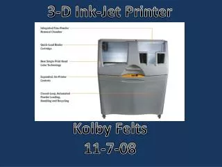
Ink-Jet Metalization. Dalla Costa Giovanni, Honkala Salomon, Kalliala Olli, Multaharju Miikka. Contents. Ink jetting Nanoparticle properties Sintering Process Electrical analysis. Jetting the ink. Generally used print heads : Thermal bubble ink-jet Piezoelectric ink-jet

E N D
Ink-Jet Metalization Dalla Costa Giovanni, Honkala Salomon,Kalliala Olli, MultaharjuMiikka
Contents • Ink jetting • Nanoparticle properties • Sintering Process • Electrical analysis
Jetting the ink Generallyusedprintheads: Thermalbubbleink-jet Piezoelectricink-jet Continuousstreamink-jet Lin,L. Bai,X.
Generallyusedprintheads: Thermalbubbleink-jet Piezoelectricink-jet Printheadsexpensive Wide range of inkfluids Controllablejettingmechanism Highreliability Long life time Professional and industrialapplications • Highnozzledensity→ compact devices, lowprintheadcosts • Inkfluidlimitations→vaporizableink • Coatingformation on the heater→degradesefficiency, reduces life time Ezzeldin. van den Bosch. Weiland.
Piezoelectric DOD printheads Bend-mode Squeeze-mode Push-mode Shear-mode Cummins. Desmulliez.
Inkjettingmechanismwithpiezoelectricactuator An electricvoltage is applied to the actuator The channelenlarges and a negativepressure is created Negative pressurewavesadvancetowards the reservoir and the nozzle Pressurewave at the reservoirreflects as a positivewave (openend) Pressurewave at the nozzlereflects and causes the meniscus to retract (closedend) Reflectedwavefrom the reservoirreaches to the middle just when the actuatordecreases the volume of the channelthuscreating an amplifiedwavefront Amplifiedwaveresults the dropinjection Ezzeldin. van den Bosch. Weiland.
Actuationpulsecontrol To avoidcrosstalk and residualvibrationsthatcausesdropvelocity and volumevariation! Crosstalkinfluencesneighboringchannelschangingtheirpressure and volume. Residualvibrations of individualchannelaffect in sequentialejections. Model-based (differentialwaveequations) feedforwardcontrol Model-free (optimizedvelocity) feedforwardcontrol Ezzeldin. van den Bosch. Weiland.
Actuationpulsecontrol Normalactuationpulseleads to variation in dropvolume and itsvelocity. Whichconsequentlyaffectsaccuracy and printingquality. Usingfeedforwardcontrolreducessuchvariations. Ezzeldin. van den Bosch. Weiland.
One nozzlejettingtest Experimentshows a single nozzleejecting 16 dropswith 48 kHz. Optimized pulseresults in congruentlinesexcluding the first and the satellite. Standard pulseproducesdropstravelingwithdifferentspeeds and many of themaremerged and misplaced. Multichannelcontrolwithasynchronousactuationneeded to minimizecrosstalk. Ezzeldin. van den Bosch. Weiland.
Minimumlinewidth Cummins. Desmulliez. Somevariableshas to be set beforehand: 1 < 1/Oh < 10 η≈ 7…20*10-3Pas σ≈ 25…35*10-3 N/m v ≈ 4…8 m/s ρ ≈ 1300 kg/m3 Pixel/D≈ 1,5 Wewant D to be as small as possible.
Nanoparticle properties The size and crystallographic structure of the nanoparticle has an essential role in determining the catalytic properties Different crystal structures (and faces) such as nanoplates, nanocubic and near-spherical has different kind of properties For silver example it has shown that the highest rate of reaction is achieved with nanocubic structure Development towards increase of the more-reactive crystal planes and a decrease in less-reactive planes. Other important properties than crystal structure are the ratio of surface area high vs (improves sintering in low temperatures), chemical stability, low chemical reactivity and high conductivity.
Nanoparticle properties: Shape factor example (silver) • The catalytic activity of the nanoparticles greatly depends on the crystal planes that the nanoparticles expose. For example in silver nanocubes shows higher activity than near-spherical or nanoplate particles because of their more reactive [100] planes. • On the other hand truncated triangle form nanoplate (A) has the most uniform structure which decreases the amount of grain boundaries increase to conductivity Fig.1. TEM images of A)truncated triangular nanoplates, B)near-spherical nanoparticles, C)nanocube [R. Xu, D.S. Wang, J.T. Zhang, Y.D. Li, Shape-dependent catalytic activity of silver nanoparticles for the oxidation of styrene, Chem. Asian J. 1 (2006) 888–893.]
Nanoparticle properties: Metals for nanoparticles Ag and Au are widely used due to their high chemical stability, low chemical reactivity and high conductivity. Copper and nickel inks have also been produced but their tendency to oxidise can affect the lifetime of the ink or require the use of additional specialized coatings in printing in inert atmospheres Ag nanoparticles can be sintered with a relatively low temperature( 150-200˚C) when printed on substrates. High surface area vs. volume is needed. For example Au nanoparticles with diameters less than 5nm are predicted to melt at 300-500˚C
Challenges in nanoparticle properties Low sintering temperatures needed due to use of flexible substrates Metals have the tendency for agglomeration which further leads to increase in viscosity. Clogging can be prevented by using specialised polymer coatings on the nanoparticles. However, removing of the surface needs high sintering temperatures which makes it unsuitable for flexible substrates. Organic coating can be removed by photonic or microwave flash sintering at low temp. As the nanoparticle size decreases so does the conductance as well. This means that the conductivity of sintered nanoparticle rarely matches to bulk form. Because of the flexible electronic device polymer substrate, the sintering temperature must be lowered to 100˚C. In this temperature it is not clear yet how low resistance can be obtained in the printed film.
Sintering • Consolidate the metallic particles in order to create a continuous conductive path • Removing of organic solvent or binder • Diffusion process • Parameters • Particle size and shape • Process environment • Time and Temperature
Thermal • Tm Nanoparticles < Tm Bulk • up to 500˚C less • T needed << Tm • 100-300˚C • Increase of sintering time is useless • Long time is needed
Q. Huang et al. / Applied Surface Science 258 (2012) 7384– 7388
Light curing • Use of a light source: IR, Camera-flash, Laser • Laser is a slow process • Difference of light absorption is important • 250 times difference in temperature increase • Substrate interaction with light is important
Q. Huang et al. / Applied Surface Science 258 (2012) 7384– 7388
K.C. Yung et al. / Journal of Materials Processing Technology 210 (2010) 2268–2272
Plasma • Need of vacuum chamber • Not for thick layer • Long time process J. Mater. Chem., 2009, 19, 3384–3388
Sheet resistance • Resistance in 3D conductor: • Combining resistivity with thickness: [ohms/square; Ω/□]
Greek-cross test structure (Van Der Pauw, 1958) Enderling et al. (2006), “Sheet resistance measurement of non-standard cleanroom materials using suspended Greek cross test structures”, IEEE Transactions on Semiconductor Manufacturing, Vol. 19 No. 1, pp. 2-9.
High-frequencycharacterization • Many HF-applications (RFID, antennas…) • Losses due to microstructure at high frequencies , depending on printing parameters, inks and substrates • Transmission-line test structures • Use vector network analyzer to determine scattering parameters Pynttäri et al. (2010), ”Application of Wide-Band Material Characterization Methods to Printable Electronics”, IEEE Transactions on Electronics Packaging Manufacturing, Vol. 33 No. 3, pp. 221-7.