Download
1 / 64
690 likes | 1.9k Vues
Norman Kwong Physics 409D. Physics of Bridges. Forces. Before we take a look at bridges, we must first understand what are forces. So, what is a force? A force is a push or a pull How can we describe forces? Lets a take a look at Newton’s law . Newton’s Laws.

E N D
Norman Kwong Physics 409D Physics of Bridges
Forces • Before we take a look at bridges, we must first understand what are forces. • So, what is a force? • A force is a push or a pull • How can we describe forces? • Lets a take a look at Newton’s law
Newton’s Laws • Sir Isaac Newton helped create the three laws of motion • Newton’s First law • When the sum of the forces acting on a particle is zero, its velocity is constant. In particular, if the particle is initially stationary, it will remain stationary. • “an object at rest will stay at rest unless acted upon”
Newton’s Laws Continued • Newton’s Second law • A net force on an object will accelerate it—that is, change its velocity. The acceleration will be proportional to the magnitude of the force and in the same direction as the force. The proportionality constant is the mass, m, of the object. • “F = mass * acceleration”
Newton’s Laws Continued • Newton’s Third law • The forces exerted by two particles on each other are equal in magnitude and opposite in direction • “for every action, there is an equal and opposite reaction”
So what do the laws tell us? • Looking at the second law we get Newton’s famous equation for force: F=ma m is equal to the mass of the object and a is the acceleration • Units of force are Newtons • A Newton is the force required to give a mass of one kilogram and acceleration of one metre per second squared (1N=1 kg m/s2)
So what do the laws tell us? • However, a person standing still is still being accelerated • Gravity is an acceleration that constantly acts on you • F=mg where g is the acceleration due to gravity
So what do the laws tell us? • Looking at the third law of motion • “for every action, there is a equal and opposite reaction” • So what does this mean? • Consider the following diagram • A box with a force due to gravity
So what do the laws tell us? • “for every action, there is an equal and opposite reaction” • A force is being exerted on the ground from the weight of the box. Therefore the ground must also be exerting a force on the box equal to the weight of the box • Called the normal force or FN
So what do the laws tell us? • From the first law: • An object at rest will stay at rest unless acted upon • This means that the sums of all the forces but be zero. • Lets look back at our diagram
The idea of equilibrium • The object is stationary, therefore all the forces must add up to zero • Forces in the vertical direction: FN and Fg • There are no horizontal forces
The idea of equilibrium • But FN is equal to – Fg (from Newton’s third law) • Adding up the forces we get FN + Fg = – Fg + Fg = 0 • The object is said to be in equilibrium when the sums of the forces are equal to zero
Equilibrium • Another important aspect of being in equilibrium is that the sum of torques must be zero • What is a torque? • A torque is the measure of a force's tendency to produce torsion and rotation about an axis. • A torque is defined as τ=DF where D is the perpendicular distance to the force F. • A rotation point must also be chosen as well.
Torques • Torques cause an object to rotate • We evaluate torque by which torques cause the object to rotate clockwise or counter clockwise around the chosen rotation point
But what if the force isn’t straight? • In all the previous diagrams, the forces have all been perfectly straight or they have all been perpendicular to the object. • But what if the force was at an angle?
Forces at an Angle • If the force is at an angle, we can think of the force as a triangle, with the force being the hypotenuse
Forces at an Angle • To get the vertical component of the force, we need to use trigonometry (also known as the x-component) • The red portion is the vertical part of the angled force (also known as the y-component • Θis the angle between the force and it’s horizontal part
To calculate the vertical part we take the sin of the force • Fvertical =F * sin (Θ) • Lets do a quick sample calculation • Assume Θ=60o and F=600N • Fvertical = 600N * sin (60o) = 519.62N
Forces at an Angle • Like wise, we can do the calculation of the horizontal (the blue) portion by taking the cosine of the angle • Fhorizontal= F * cos (Θ) • Fhorizontal= 600N * cos (60o) =300N
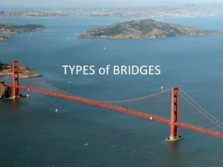
Bridges • Now that we have a rough understanding of forces, we can try and relate them to the bridge. • A bridge has a deck, and supports • Supports are what holds the bridge up • Forces exerted on a support are called reactions • Loads are the forces acting on the bridge
Bridges • A bridge is held up by the reactions exerted by its supports and the loads are the forces exerted by the weight of the object plus the bridge itself.
Beam Bridge • Consider the following bridge • The beam bridge • One of the simplest bridges
What are the forces acting on a beam bridge? • So what are the forces? • There is the weight of the bridge • The reaction from the supports
Forces on a beam bridge • Here the red represents the weight of the bridge and the blue represents the reaction of the supports • Assuming the weight is in the center, then the supports will each have the same reaction
Forces on a beam bridge • Lets try to add the forces • Horizontal forces (x-direction): there are none • Vertical forces (y-direction): the force from the supports and the weight of the bridge
Forces on a beam bridge • Lets assume the bridge has a weight of 600N. • From the sums of forces Fy = -600N + 2 Fsupport=0 • Doing the calculation, the supports each exert a force of 300N
To meet the other condition of equilibrium, we look at the torques (τ=DF) with the red point being our rotation point • τ= (1m)*(600N)-(2m)*(600N)+(3m)*(600N) = 0
Limitations • With all bridges, there is only a certain weight or load that the bridge can support • This is due to the materials and the way the forces are acted upon the bridge
What is happening? • There are 2 more other forces to consider in a bridge. • Compression forces and Tension forces. • Compression is a force that acts to compress or shorten the thing it is acting on • Tension is a force that acts to expand or lengthen the thing it is acting on
There is compression at the top of the bridge and there is tension at the bottom of the bridge • The top portion ends up being shorter and the lower portion longer • A stiffer material will resist these forces and thus can support larger loads
Bridge Jargon • Buckling is what happens to a bridge when the compression forces overcome the bridge’s ability to handle compression. (crushing of a pop can) • Snapping is what happens to a bridge when the tension forces overcome the bridge’s ability to handle tension. (breaking of a rubber band) • Span is the length of the bridge
How can deal with these new forces? • If we were to dissipate the forces out, no one spot has to bear the brunt of the concentrated force. • In addition we can transfer the force from an area of weakness to an area of strength, or an area that is capable of handling the force
A natural form of dissipation • The arch bridge is one of the most natural bridges. • It is also the best example of dissipation
In a arch bridge, everything is under compression • It is the compression that actually holds the bridge up • In the picture below you can see how the compression is being dissipated all the way to the end of the bridge where eventually all the force gets transferred to the ground
Compression in a Arch • Here is another look at the compression • The blue arrow here represents the weight of the section of the arch, as well as the weight above • The red arrows represent the compression
Arches • Here is one more look at the compression lines of an arch
A Stronger Bridge • Another way to increase the strength of a bridge is to add trusses • What are trusses?? • A truss is a rigid framework designed to support a structure • How does a truss help the bridge? • A truss adds rigidity to the beam, therefore, increasing it’s ability to dissipate the compression and tension forces
So what does a truss look like? • A truss is essentially a triangular structure. • Consider the following bridge (Silver Bridge, South Alouette River, Pitt Meadows BC )
Trusses • We can clearly see the triangular structure built on top of a basic beam bridge. • But how does the truss increase the ability to handle forces? • Remember a truss adds rigidity to the beam, therefore, increasing it’s ability to dissipate the compression and tension forces
Trusses • Lets take a look at a simple truss and how the forces are spread out
Lets take a look at the forces here • Assumptions: all the triangles are equal lateral triangles, the angle between the sides is 60o
Sum of torques = (1m)*(-400N) + (3m)*(-800N)+(4m)*E=0 • E=700N • Sum of forces = AY + E - 400N - 800N • Ay=500N
Now that we know how the forces are laid out, lets take a look at what is happening at point A • Remember that all forces are in equilibrium, so they must add up to zero
Sum of Fx=TAC + TAB cos 60o = 0 • Sum of Fy=TAB sin 60o +500N = 0 • Solving for the two above equations we get • TAB = -577N TAC= 289N
Compression and Tension • TAB = -577N • TAC= 289N • The negative force means that there is a compression force and a positive force means that there is a tension force
Sum of Fx = TBD + TBC cos 60o + 577 cos 60o= 0 • Sum of Fy = -400N + 577sin60o –TBCsin60o=0 • Once again, solving the two equations • TBC=115N TBD=-346N
Tension and Compression • TBC=115N • TBD=-346N • The negative force means that there is a compression force and a positive force means that there is a tension force
Forces in a Truss • If we calculated the rest of the forces acting on the various points of our truss, we will see that there is a mixture of both compression and tension forces and that these forces are spread out across the truss