Download
1 / 24
240 likes | 386 Vues
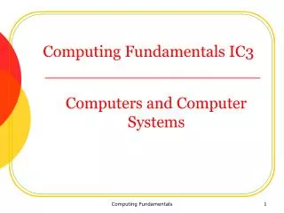
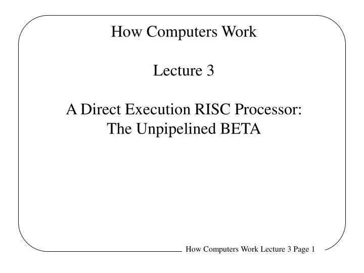
How Computers Work Lecture 3 A Direct Execution RISC Processor: The Unpipelined BETA. What you can do with very little:. Each instruction class can be implemented using a few simple components. Components:. r0. r1. r2. 32 bits. r31. always 0. Review: b Model of Computation.

E N D
How Computers WorkLecture 3A Direct Execution RISC Processor:The Unpipelined BETA
What you can do with very little: Each instruction class can be implemented using a few simple components. Components:
r0 r1 r2 32 bits r31 always 0 Review: b Model of Computation Fetch/Execute Loop: Processor State Instruction Memory PC • Fetch <PC> • PC ¬ <pc> + 1 • Execute fetched instruction • Repeat! 32 bits (4 bytes) next instr
OPCODE Ra Unused Rb Rc OPCODE Ra 16 bit Constant Rc Review: BETA Instructions Two 32-bit Instruction Formats:
OPCODE Ra Unused Rb Rc OPCODE Ra 16 bit Constant Rc Review: b ALU Operations SIMILARLY FOR: What the machine sees (32-bit instruction word): • • SUB, SUBC • • (optional) • MUL, MULC • DIV, DIVC • BITWISE LOGIC: • • AND, ANDC • • OR, ORC • • XOR, XORC • SHIFTS: • • SHL, SHR, SAR • (shift left, right; • shift arith right) • COMPARES • CMPEQ, CMPLT, CMPLE What we prefer to see: symbolic ASSEMBLY LANGUAGE ADD(ra, rb, rc) rc ¬ <ra> + <rb> “Add the contents of ra to the contents of rb; store the result in rc” Alternative instruction format: ADDC(ra, const, rc) rc ¬ <ra> + sext(const) “Add the contents of ra to const; store the result in rc”
A Descending Data Flow View of the Beta PC Q Operate class: Rc <- <Ra> op <Rb> XADDR RA1 Memory RD1 BRZ(R31,XADDR,XP) ISEL 0 1 31:26 25:21 20:5 9:5 4:0 OPCODE RA C RB RC +1 0 1 OPCODE Register File RA1 RD1 Register File RA2 RD2 SEXT ASEL BSEL 0 1 2 1 0 A ALU B ALUFN A op B Z RA2 Memory RD2 PCSEL 0 1 0 1 2 WDSEL D PC WD Memory WA WD Register File WA RC WE WEMEM WE WERF
Combinational Read Port on Memory Address A Memory Q <Address>
Data Register • Works like a camera • D = image • Q = picture • E = On/Off Switch • clock = shutter release button Q D E Clock
D Register w/ Enable D Q E clk clk clk Q Q D D E E
WD 32 32 2-Port Register File (independent Read addresses) RA A RD <A> RA1 RA2 5 WA Write Address CLK Register File WE Write Enable WE (2-port) WD Write Data 32 WA A CLK RD1 RD2 new <A> Note: <R31> Always ZERO! (Independent Read Data) • What if (say) WA=RA1??? • RD1 reads value from last cycle!
Selector (a.k.a. Multiplexor / MUX) • Output Q is selected to be 1 of N inputs • N is a power of 2 • K select inputs, K = log2(n) • May be ganged to select one W-bit word out of N multi-bit words D2 D1 D0 DN-1 DN-1 D2 D1 D0 W . . . . . . S S K K W Q = Ds Q = Ds
A Descending Data Flow View of the Beta PC Q Operate class: Rc <- <Ra> op <Rb> XADDR RA1 Memory RD1 BRZ(R31,XADDR,XP) ISEL 0 1 31:26 25:21 20:5 9:5 4:0 OPCODE RA C RB RC +1 0 1 OPCODE Register File RA1 RD1 Register File RA2 RD2 SEXT ASEL BSEL 0 1 2 1 0 A ALU B ALUFN A op B Z RA2 Memory RD2 PCSEL 0 1 0 1 2 WDSEL D PC WD Memory WA WD Register File WA RC WE WEMEM WE WERF
A Descending Data Flow View of the Beta PC Q Operate class: Rc <- <Ra> op C XADDR RA1 Memory RD1 BRZ(R31,XADDR,XP) ISEL 0 1 31:26 25:21 20:5 9:5 4:0 OPCODE RA C RB RC +1 0 1 OPCODE Register File RA1 RD1 Register File RA2 RD2 SEXT ASEL BSEL 0 1 2 1 0 A ALU B ALUFN A op B Z RA2 Memory RD2 PCSEL 0 1 0 1 2 WDSEL D PC WD Memory WA WD Register File WA RC WE WEMEM WE WERF
Review: b Branches • Conditional: rc = <PC>+1; then • BRNZ(ra, label, rc) if <ra> nonzero then • PC <- <PC> + displacement • BRZ(ra, label, rc) if <ra> zero then • PC <- <PC> + displacement • Unconditional: rc = <PC>+1; then • BRZ(r31, label, rc) PC <- <PC> + displacement • Indirect: rc = <PC>+1; then • JMP(ra, rc) PC <- <ra> Note: “displacement” is coded as a CONSTANT in a field of the instruction!
A Descending Data Flow View of the Beta PC Q Rc <- <PC>+1; if <Ra>=0 then PC <- <PC>+C XADDR RA1 Memory RD1 BRZ(R31,XADDR,XP) ISEL 0 1 31:26 25:21 20:5 9:5 4:0 OPCODE RA C RB RC +1 0 1 OPCODE Register File RA1 RD1 Register File RA2 RD2 SEXT ASEL BSEL 0 1 2 1 0 A ALU B ALUFN A op B Z RA2 Memory RD2 PCSEL 0 1 0 1 2 WDSEL D PC WD Memory WA WD Register File WA RC WE WEMEM WE WERF
A Descending Data Flow View of the Beta JMP: Rc <- <PC>+1; PC <- <Ra> + C PC Q XADDR RA1 Memory RD1 BRZ(R31,XADDR,XP) ISEL 0 1 31:26 25:21 20:5 9:5 4:0 OPCODE RA C RB RC +1 0 1 OPCODE Register File RA1 RD1 Register File RA2 RD2 SEXT ASEL BSEL 0 1 2 1 0 A ALU B ALUFN A op B Z RA2 Memory RD2 PCSEL 0 1 0 1 2 WDSEL D PC WD Memory WA WD Register File WA RC WE WEMEM WE WERF
Review: b Loads & Stores LD(ra, C, rc) rc ¬ < Mem[<ra> + sext(C)] > ST(rc, C, ra) Mem[<ra> + sext(C)] ¬ <rc> Old New ST(ra, C, rc) Mem[<rc> + sext(C)] ¬ <ra>
Straightening Out Store • Old Format: ST(Rc, C, Ra) • Mem[<Ra> + C] <- <Rc> • ST(R1, 2, R3) means Mem[<R3> + 2] <- <R1> • New Format: ST(Ra, C, Rc) • Mem[<Rc> + C] <- <Ra> • ST(R1, 2, R3) means Mem[<R3> + 2] <- <R1> • Both versions of Store work “from left to right”in assembly language. • Difference is only in the binary encoding of the instruction, and the hardware implementation’s decoding of the binary encoding.
A Descending Data Flow View of the Beta PC Q LD: Rc <- Mem[<Ra>+C] XADDR RA1 Memory RD1 BRZ(R31,XADDR,XP) ISEL 0 1 31:26 25:21 20:5 9:5 4:0 OPCODE RA C RB RC +1 0 1 OPCODE Register File RA1 RD1 Register File RA2 RD2 SEXT ASEL BSEL 0 1 2 1 0 A ALU B ALUFN A op B Z RA2 Memory RD2 PCSEL 0 1 0 1 2 WDSEL D PC WD Memory WA WD Register File WA RC WE WEMEM WE WERF
A Descending Data Flow View of the Beta PC Q ST: Mem[<Rc>+C] <- <Ra> XADDR RA1 Memory RD1 BRZ(R31,XADDR,XP) ISEL 0 1 31:26 25:21 20:5 9:5 4:0 OPCODE RA C RB RC +1 0 1 OPCODE Register File RA1 RD1 Register File RA2 RD2 SEXT ASEL BSEL 0 1 2 1 0 A ALU B ALUFN A op B Z RA2 Memory RD2 PCSEL 0 1 0 1 2 WDSEL D PC WD Memory WA WD Register File WA RC WE WEMEM WE WERF
LDRLoadRelative • Used for loading large (32 bit) constants with data from the instruction stream. • Depends on the fact data and instruction memory are ports of one main memory. • Use: LDR (label, Rc) • RTL Description: Rc <- <Mem[<NextPC> + Offset]> • Note that Ra is ignored, Offset is calculated from label • … • LDR (label, R1) • BR (label + 1) • label: 123456789 • …
A Descending Data Flow View of the Beta PC Q LDR: Rc <- Mem[<PC>+1+C] XADDR RA1 Memory RD1 BRZ(R31,XADDR,XP) ISEL 0 1 31:26 25:21 20:5 9:5 4:0 OPCODE RA C RB RC +1 0 1 OPCODE Register File RA1 RD1 Register File RA2 RD2 SEXT ASEL BSEL 0 1 2 1 0 A ALU B ALUFN A op B Z RA2 Memory RD2 PCSEL 0 1 0 1 2 WDSEL D PC WD Memory WA WD Register File WA RC WE WEMEM WE WERF
Control Logic Truth Table We can specify it via a table of the form ... Control Logic Inputs: BRZ OPCODE OP OPC LD ST BRNZ JMP LDR (Illegal) 0 0 1 1 Z Control Logic Outputs: PCSEL RA2SEL ASEL BSEL WDSEL ALUFN Wr WERF WASEL YOU should be able to fill in this table!