Download
1 / 43
440 likes | 448 Vues
This article discusses the concepts of soft state and hard state in network protocols, highlighting their advantages, disadvantages, and crash scenarios. It also covers the process of receivers joining the shared tree, hosts sending data to a group, and switching to the shortest path tree. Additionally, it addresses the RP bootstrap problem and how routers are chosen as RPs for a group.

E N D
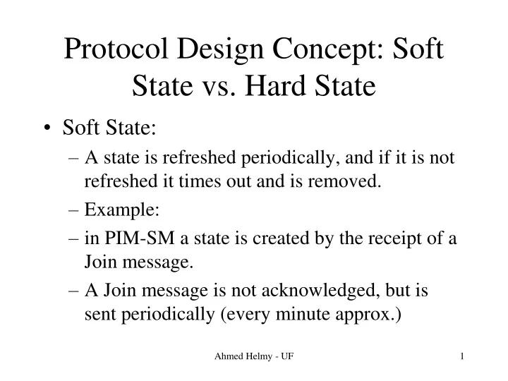
Protocol Design Concept: Soft State vs. Hard State • Soft State: • A state is refreshed periodically, and if it is not refreshed it times out and is removed. • Example: • in PIM-SM a state is created by the receipt of a Join message. • A Join message is not acknowledged, but is sent periodically (every minute approx.) Ahmed Helmy - UF
A router maintains an entry timer for every state created. • When a router receives a Join it restarts (or refreshes) that timer. • When a router does not receive a Join for approx. 3 x Join refresh period (approx 3 min.s) it times out the timer and the entry is removed. Ahmed Helmy - UF
Hard state • A state in a router is created once, and it remains until another message is sent to remove it. • Usually uses an acknowledged message, • Simple example: • DVMRP uses a graft message to create a state. Ahmed Helmy - UF
The graft message is acknowledged. • When a router receives a graft, it creates the state, and the state remains until a prune is sent to remove the forwarding state in that router. Ahmed Helmy - UF
Advantages and disadvantages • For soft state: • Since, in general, it is not acknowledged, it may lead to 'join latency'. • For example, if a receiver joins the group and the join is lost, it has to wait until the next refresh period to send another join. Ahmed Helmy - UF
In hard state: • Since, in general, it is acknowledged, it incurs less join latency (since the ack timer is probably 3 seconds while the refresh timer is approx 1 min.). • The main advantage for soft state (vs. hard state) is its robustness to failures. Ahmed Helmy - UF
Crash scenarios: • If A sends a graft message, it gets acknowledged, and B creates state • A crashes and loses state • State will remain permanently in B • Packets will keep on getting to A unless/until a prune is sent Ahmed Helmy - UF
If router B crashes and comes back up again, there is no way to recreate the state in B (because A already got ack for its graft). • So DVMRP uses periodic broadcast to take care of this situation. • In PIM-SM, the soft state (periodic refresh) mechanisms take care of the above crash scenarios. Ahmed Helmy - UF
Receivers Joining the Shared Tree 3. Create (*,G) entry: Multicast address=G RP-address=C,WC=1,RP=1 outgoing interface list={1} incoming interface=2 D 7. Create (*,G) entry: Multicast address=G RP-address=C,WC=1,RP=1 outgoing interface list={1} incoming interface=Null 2. IGMP Host- Membership Report for G 4. Send Join/Prune message to B: Multicast address=G Join={C,WC,RP} Prune=Null Host 2 1 2 1 3 1 Receiver ... A B C LAN PIM DR/IGMP Querier for LAN Rendezvous Point (RP) for group G 1. IGMP Host- Membership Query 6. Send Join/Prune message to C: Multicast address=G Join={C,WC,RP} Prune=Null 5. Create (*,G) entry: Multicast address=G RP-address=C,WC=1,RP=1 outgoing interface list={1} incoming interface=3 Ahmed Helmy - UF
Host Sending to the Group 1. Data packets for G Host 2. Create (S,G) entry incoming interface=1 DR for LAN(B) 1 Receiver A 2 1 LAN(B) D Host 3. Encapsulate Data packets in Register messages and unicast to RP(C) Source 2 12. When receiver Register-Stop stop encapsulating packets 5. If (*,G) state exists then decapsulate Registers and forward packets to oiflist (*,G) 4. Initiate (S,G) packet counter 10. Update (S,G) entry: add 2 to outgoing interface list Rendezvous Point (RP for group G 2 1 1 C X 2 9. Send Join/Prune message to D: Multicast address=G Join={S},Prune=Null 6. If Register data rate > Threshold then create (S,G) entry: outgoing list=oiflist (*,G)-{2} incoming interface=2 RP=0,SPT=0 7. Send Join/Prune message to X: Multicast address=G Join={S}, Prune=Null 8. Create (S,G) entry: outgoing list={1} incoming interface=2 11. When receive (S,G) native packets set SPT bit for (S,G) entry, & trigger Register-Stop message to D Ahmed Helmy - UF
Switching to the Shortest Path Tree 1. Receive S’s packets on shared RP tree Initiate packet count If data rate > Threshold then: Create (S,G) entry: outgoing interface list={1} incoming interface=2 RP=0,WC=0,SPT=0 5. Add interface 2 to the outgoing interface list of (S,G) entry First Hop Router for S 4. Send Join/Prune message to D: Multicast address=G Join={S} Prune=Null D Host 2 1 Source (S) 2. Send Join/Prune message to B: Multicast address=G Join={S} Prune=Null 7. Create (S,G) entry: oif list=oif(*,G)-{1} RP-bit=1 Host 2 2 1 2 1 3 1 Receiver A B C LAN PIM DR/IGMP Querier for LAN Rendezvous Point (RP) for group G 6. After receiving packets from D: Set (S,G)’s SPT-bit=1 and, send Join/Prune message to C: Multicast address=G Join=Null Prune={S,RP-bit} 3. Create (S,G) entry: outgoing interface list={1} incoming interface=2 RP=0,WC=0,SPT=0 Ahmed Helmy - UF
The RP Bootstrap Problem • Which router to use as RP for a group? • A set of well-connected routers are configured as Candidate-RPs for group(s) per domain • A manageable number of RPs is chosen • RPs advertise candidacy for group-prefix (not per group), for scalability • Periodic advertisement of candidacy to capture dynamics and unreachability • Who maintains/updates/distributes this info? Ahmed Helmy - UF
RP Bootstrap Design Rationale • Host model: • hosts need only “logical” multicast group address to send or receive • RP address is network (not logical) address • Routers should map group address to RP address and adapt to unreachability/change of RP Ahmed Helmy - UF
RP Bootstrap Design Rationale • No “on-demand” retrieval of RP info to avoid start-up phase • can’t join or send until DR gets RP address • “bursty source” problem: • packets are lost until DR identifies active RP • global distribution of explicit group to RP mapping and reachability not scalable • Use a-priori status distribution • like unicast routing, periodic liveness tracking • distribute RP-list throughout the domain Ahmed Helmy - UF
Choosing RPs: The Bootstrap Mechanism • PIMv2 has a Bootstrap router election procedure • The Bootstrap router receives Candidate-RP messages from potential RPs • Bootstrap router sends Bootstrap messages which contain a list of reachable Candidate-RPs • All PIM routers receive these Bootstrap messages • DRs obtain group-to-RP mapping (when hosts join or send to the group) through a hash algorithm Ahmed Helmy - UF
RP Bootstrap Mechanism • RP location need not be optimized, but consistent RP mapping and adaptation to failures is criticial • all routers (within PIM domain) must associate a single active RP with a multicast group • Routers use ‘algorithmic mapping’of Group address to RP from manageably-small set of RPs known throughout domain Ahmed Helmy - UF
RP Booststrap Mechanism • Each candidate RP indicates liveness to the Bootstrap Routerin the PIM domain • Bootstrap Router distributes set of reachable candidate RPs to all PIM routers in domain. • Each PIM router uses the same hash function and set of RPs to map a particular multicast group address to that group’s RP. Ahmed Helmy - UF
Dynamic Bootstrap Router Election • Simple bridge-like spanning-tree election algorithm • A set of well-connected routers are configured as Candidate Bootstrap Routers (C-BSRs) per domain • C-BSRs originate PIM hop-by-hop Bootstrap messages with IP address and preference value. • Bootstrap messages are exchanged by all PIM routers within domain (flooded with RPF check) • Most preferred (or highest numbered) reachable C-BSR is elected Ahmed Helmy - UF
Routers use hash function to mapGroup address to RP • Hash function • input: group address G and address of each candidate RP in RP set (with optional Mask) • output: Value computed per candidate RP in RP set • RP with highest value is the RP for G • Desirable characteristics • minimize remapping when RP reachability changes — remap only those that lost RP • load spreading of groups across RPs Ahmed Helmy - UF
Adaptation to RP Unreachability • When Candidate RP fails/unreachable • Bootstrap Router times it out • Bootstrap message distributed with updated RP set • Routers hash affected groups to different RP Ahmed Helmy - UF
References • RFC 2362/2117 • http://catarina.usc.edu/pim Ahmed Helmy - UF
Multicast and the Internet • Initially there was the MBONE • Short-term inter-domain solution based on PIM-SM, MBGP and MSDP • Longer-term architecture BGMP Ahmed Helmy - UF
The Internet's Multicast Backbone (MBONE) The MBONE is an interconnect of subnets and routers that support IP-multicast. The goal of the MBONE was: initially: to construct an IP multicast test-bed as it became popular: gradual deployment of multicast applications without waiting for the ubiquitous Internet multicast deployment Ahmed Helmy - UF
The MBONE is rapidly growing 40 subnets in 4 countries in ‘92 > 2800 subnets in over 25 countries in April ‘96 The MBONE is a virtual network layered on top of a subset of the Internet. It is composed of islands of multicast-capable routers connected to other islands by virtual point-to-point links called “tunnels.” Ahmed Helmy - UF
Tunneling • Tunnels allow multicast traffic to pass through the non-multicast-capable parts of the Internet. • Multicast packets are encapsulated as IP-in-IP, so they look like normal unicast packets to intermediate routers. • Encapsulation is added on entry to a tunnel and stripped off on exit from a tunnel. Ahmed Helmy - UF
Multicast islands connected through tunnels Ahmed Helmy - UF
The MBONE and the Internet have different topologies, so: multicast routers execute a separate routing protocol to forward multicast packets. Much of the MBONE routers run DVMRP Portions of the MBONE run: MOSPF Protocol-Independent Multicast (PIM) Ahmed Helmy - UF
MBONE Limitations • “Mbone currently using DVMRP, which was never intended for, and is ill-suited to, this task • known problems of DV with large networks • broadcast & prune approach ‘undesirable’ for interdomain routing”, S. Deering. • Suggested solution: • Use sparse-mode concepts • Use 2-level hierarchy (as in unicast) Ahmed Helmy - UF
Recent Deployment • Use PIM-SM as intra-domain multicast routing protocol • Use MBGP (Multicast BGP) to distribute inter-domain multicast routes • Use MSDP (Multicast Source Discovery Protocol) between RPs in different domains Ahmed Helmy - UF
MBGP • BGP (RFC 1771) used for unicast routing to: • aggregate and abstract routes for scalability • provide inter-domain routing policies • BGP4+ (RFC 2283) can carry multicast routes • multicast routers need only know • - internal topology and - paths to reach other domains • provides topology info for multicast routes that may be different than unicast routes Ahmed Helmy - UF
Problem Connecting PIM-SM domains Sources register with RP in their domain and receivers join towards the RP in their domain S R RPB RPA Domain A (PIM-SM) Domain B (PIM-SM) No way for receiver in domain B to know about sources in domain A and vice versa Ahmed Helmy - UF
MSDP • To tie PIM-SM trees in different domains • every RP has MSDP peers (RPs in other domains) • when a source registers to the RP it conveys this info to its MSDP peers through TCP and SA messages • this info is RPF-flooded to other domains • an RP with members in its domain joins towards src Ahmed Helmy - UF
AS 1 AS 2 (S,G) Joins towards RP2 RP1 Creates State RP1 RP2 Last hop router sends (S,G) Register to RP1 Source S Receiver R Normal SM Ahmed Helmy - UF
RP1 RP2 Source S Receiver R Peering MSDP Peering MSDP Peering o Between RPs o Over TCP Ahmed Helmy - UF
RP1 RP2 Source S Receiver R Sending SA Msgs RP1 Sends (S,G) SA message RP1 Creates State (S,G) Joins towards RP2 MSDP Peering Last hop router sends (S,G) Register to RP1 Ahmed Helmy - UF
RP2 Joins (S,G) Source Tree RP1 RP2 RP1 Creates State (S,G) Joins towards RP2 (S,G) Joins Last hop router sends (S,G) Register to RP1 Source S Receiver R Joining the Source Tree Ahmed Helmy - UF
RP1 RP2 Source S Receiver R Forwarding Packets Ahmed Helmy - UF
Limitations • Short-term solution that doesn’t scale well! Ahmed Helmy - UF
New Developments in Inter-Domain Multicast Routing • BGMP (Border Gateway Multicast Protocol): • PIM-SM-like inter-domain multicast routing protocol • builds bi-directional shared trees of domains • each tree has a ‘root domain’ (like an RP) • MASC (Multicast Address Set Claim): • mechanism to associate addresses with root domains • MBGP: • extends BGP to convey ‘address-range to root’ mapping to border routers Ahmed Helmy - UF
BGMP • Bi-directional shared trees rooted at domains • Border routers send joins and data toward root domain for mcast address in packet • Mapping of multicast address to root domain obtained from BGP4+ MRIB • Source specific branches only where “needed” Ahmed Helmy - UF
AS1 ISP 1 Sender/Rcvr Group Initiator BGMP tree Ahmed Helmy - UF
BGMP Reference • For more references: • Sigcomm ‘99 [Kumar et al.] • The PIM project: • http://www.cise.ufl.edu/~helmy/projects.html#pim Ahmed Helmy - UF