Download
1 / 70
700 likes | 863 Vues
New Instrumentation Concepts – Ground-based Optical Telescopes. Keith Taylor (IAG/USP) September, 2010. Synopsis of Lectures. Basic Principles: Fundamentals ; Basic Technologies; Basic Techniques Introduction to Astronomical Instrumentation Imaging ; Spectroscopy ; Interferometry

E N D
New Instrumentation Concepts – Ground-based Optical Telescopes Keith Taylor (IAG/USP) September, 2010
Synopsis of Lectures • Basic Principles: • Fundamentals ; Basic Technologies; Basic Techniques • Introduction to Astronomical Instrumentation • Imaging ; Spectroscopy ; Interferometry • Advanced Instrumentation Techniques • 2D techniques ; 3D techniques ; Hybrid techniques ; Classical Spectroscopy ; Integral Field Spectroscopy ; Robotics
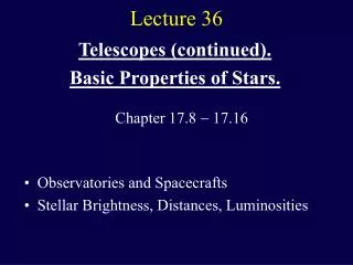
What is the purpose a telescope? • Collect and analyze photons over a region of sky • At what wavelength ()? • Over what bandwidth ()? • At what Spectral Resolution ()? • Over what Field of View (FoV)? • At what Spatial Resolution? • Point sources? Single or Multiple? or Diffuse? • At what Temporal Resolution? • Polarization of source? • Note: Objects generally very distant and extremely faint • Every photon counts • Time to do observation/experiment must be << a human life-time • # of telescopes << # of astronomers who want to use them • # telescopes may be >> # of good ideas on how to use them?
What’s the message here? • Telescopes are a rare and expensive resource; • They are not simply there to gather photons that would otherwise be best left in the most secure storage medium in existence (the sky); • Emphasis should be on effectiveness rather than efficiency; • Access to telescopes is highly competitive • Not always a good match between observational goals to available instrumentation; • Conflict between general purpose and targeted instrumentation; • As instrumentation becomes more powerful there is a move from studies of individual objects to statistically astronomy and cosmology.
The “Art” of Observational Astronomy • The detection of ultra-distant objects • The detection of ultra-faint signals • Plane-wave of light from distant objects • Has to be intersected and focused into an instrument of some type which analyses the information in a useful way. • How can this be done most effectively? • Make the collecting area as big as possible (?); • Use an instrument that is optimized for the collection of the required information. • eg: Imaging ; Spectroscopy ; Interferometry ; Polarimetry • Object morphology - Single or Multiple or Diffuse? • What about the time domain?
Limits to spatial Resolution of a Telescope Resolving power: Wave nature of light => The telescope aperture produces fringe rings that set a limit to the resolution of the telescope. Resolving power = minimum angular distance min between two objects that can be separated. min = 1.22 (/D) min For optical wavelengths, this gives min ~0.1 arcsec / D[m]
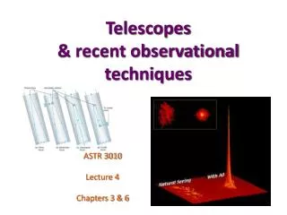
Seeing (ground-based telescope) Weather conditions and turbulence in the atmosphere set further limits to the quality of astronomical images. Spatial resolution can only be recovered with Adaptive Optics Bad seeing Good seeing
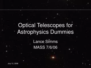
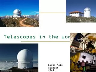
The Best Location for a Telescope? (not any more!) Mount Wilson Mount Palomar Kitt Peak Far away from civilization – to avoid light pollution Chilean Andes ; Island Volcanos (Hawaii or La Palma)
The Best Location for a Telescope Paranal Observatory (ESO), Chile On high mountain-tops – to avoid atmospheric turbulence (seeing) and other weather effects
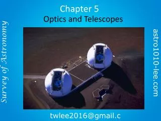
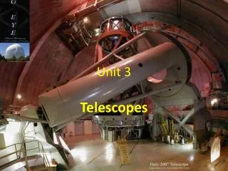
So what does a “modern” telescope look like? Secondary mirror Traditional primary mirror: sturdy, heavy to avoid distortions.
The 4m class (c1975) The 4-m Mayall Telescope at Kitt Peak National Observatory (Arizona) Equatorial mount (1 axis of rotation)
Advances in Telescope Design (c1980 and beyond) Modern computer technology has made possible significant advances in telescope design: 1. Lighter mirrors with lighter support structures, to be controlled dynamically by computers Floppy mirror Segmented mirror 2. Simpler, stronger mountings (“Alt-azimuth mountings”) to be controlled by computers
Examples of Modern Telescope Design of the Large Binocular Telescope (LBT) The Keck I telescope mirror
Examples of Modern Telescope Design (2) The Very Large Telescope (VLT) 8.1-m mirror of the Gemini Telescopes
The Future(Needs AO to exploit D4 science) TMT – 30m (Caltech, UC, Canada) E-ELT – 42m (ESO) GMT – 25m (Multi-institutes US+)
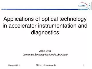
THE ELECTROMAGNETIC SPECTRUM • Wavelength, frequency, energy units (convenient working units in any band typically yield numerical values in the range 1–10000) • Radio: cm, GHz, or MHz • Far-IR/Sub-mm: μmor mm • IR: μm • UVOIR: °A, μm, or nm • EUV: eV or °A • X-Ray: keV • Gamma Ray: MeV
The Electromagnetic Spectrum Wavelength Frequency High flying air planes or satellites Need satellites to observe
UVOIR Astronomy Uniqueness: Best developed instrumentation; Best understood astrophysically; Highest density of astrophysical information; By accident or design? – don’t ask S. Hawkins? Provides prime diagnostics on the most important physical tracers. UVOIR observations/identifications are almost always prerequisites to a thorough understanding of cosmic sources in other EM bands.
The generic telescope/spectrograph Focal Plane collimator camera detector Dispersing element Slit Telescope Spectrograph
Where is the re-imaged pupil?(= Image of Telescope formed by Collimator) Pupil Det Camera Collimator
1() () x () y ly lx Astro. Spectrograph (Schematic) D A (D) a (d) Det F2 F1 F1 Cam Coll T’scope
Fundamental Parameters • A = Telescope collecting area • D = diameter • = solid angle subtended at telescope aperture • = angle • a = beam area of collimator • d = diameter • 1 = acceptance solid angle at spectrograph • = angle • F1 = focal-ratio of telescope • F2 = focal-ratio of spectrograph camera • dp = pixel-size pf detector • of linear dimensions: lx-by-ly
Pre-area detectors: Says nothing about pixelation of data • The wavelength resolving power (R) of an astronomical spectrograph is given by: R = /d • Etendue (information flux) through any optical system (eg: telescope to spectrograph) is conserved and given by: A = a1 (or: D. = d.) (1) • Source with surface brightness, (ergs.s-1.cm-2.sterad-1) then flux gathered by spectrograph is: ..A. (ergs.s-1) (2) where: • A = Etendue = “Information Throughput” • Luminosité = A (= L) • LR-product = AR (a general “figure of merit”)
CCD Array Camera Semiconductor fabrication limits the size of a CCD detector To get a large area need to mosaic detectors together Subaru Mosaic CCD Camera
From equn.(1) Nyquist sampling Now includes area detector advantage NB: A implies single circular apertures, but … • Area detectors (eg: CCDs) allows • 1-D (y) of spatial information • 1-D (x) of spectral () information • Now a given pixel-size (dp) is given by: dp = d.F2.d = D.F2.d(3) • While spatial and spectral multiplexes are given by: Mx = lx/(2dp) ; My = ly/(2dp) (4) • We can therefore re-define a figure of merit as: AR Mx My (5) where: • A = Entendue • A = Luminosité • A.R = the LR-product • So: (LR) Mx My = AR Mx My (6)
From equations 1 to 6our figure of merit becomes … Angular Dispersion Pixel Dispersion Bigger telescopes give smaller pixels on the sky Cram more light into a given pixels (LR) Mx My = ..(/4)2.D..(d/d).d. Mx My(7) = ..(/4)2.D..(dp/d).(1/F2). Mx My(8) = .(/4)2.R.(lx.ly/4).(1/F22)(9) • This figure of merit implies that there is no advantage to • Large telescopes (D) or • Large Spectrographs (d) • But it is dependant on: • Camera f-ratio (F22) which should be minimized (ie: as fast as possible), and • Detector format (lx.ly) which should be maximized
dp = D.F2.d So … need larger telescope to deliver finer spatial resolution • Practical constraints: • Input aperture: x~ 1” (seeing limit) • Pixel-size: dp ~20m (fabrication constraint) • Camera f-ratio: F2> 2 (refractive) and > 1 (Catadioptic) • Constraints 1&2 (with Equn (3)) implies • F2.D ~ 8m … and even 8m requires f/1 (Schmidt) cameras • and what do you do for ELTs • Conclusion: • Large telescopes do not improve information gathering capacity • but do give improvements in “Information Density” in units of ergs.s-1.cm-2.arcsec-2 • Need to offer improvements in spatial resolution through the use of Adaptive Optics (AO)
The Large Telescope Game • Once D > 4m then either (or both) • F2 < 2 (not easy) • < 1” (requires AO) • For D ~8m and above, AO is essential • Unless objects are spatially resolved (like faint galaxies) • For spectroscopy (gratings or FPs) • d/d is intrinsic (ie: fixed for a given configuration) • This means that D d (1/F2) … double bind: • The larger the telescope … • The larger the spectrograph, and … • The faster the camera • Spectrograph cost Dn where n is “large”!
The Spectrograph Using a prism (or a grating), light can be split up into different wavelengths (colors!) to produce a spectrum. Spectral lines in a spectrum tell us about the chemical composition and other properties of the observed object
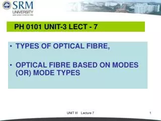
Grating Spectrograph • Simple grating spectrograph • Spectrum extracted along a slit so ‘imaging’ in one dimension • Off source light along slit used to measure and subtract sky background
What you get • Optical long slit spectrum of a galaxy • Minimal data reduction so far • Can see galaxy, bad pixels and sky lines • Need off source signal to measure and remove Target Sky lines Target
Considerations for Spectroscopy • Basic parameters - resolution and central wavelength for spectrum • Slit width (if selectable) affects resolution • Wavelength range • Set by combination of detector geometry and resolution • Some spectrographs provide large range others (eg. PACS on Herschel) provide only a few 1000kms-1 range, so centering on your line critical
Detectors for Opical/near-IR(current) • Photon Counters: • Image tube + TV camera + real-time discrimination (not solid state) • eg: IPCS - c70s to c80s • CCDs now dominate - Hi QE but … • Integrate signal on detector – no time resolution • Finite read-noise • Finite read-time • EMCCDs – new generation of Photon Counters • CCD-like QEs • V. high frame-rates
DQE - the key to gooddetectors • Detector quantum efficiency - the fraction of incident photons detected - is the key measure for the effectiveness of a detector; • Traditional photographic plates, while large in size, have DQE of only about 10% • CCDs and similar semiconductor devices can have DQE as high as 90% (though wavelength dependent) • Like having a telescope with 9 times the collecting area
CCDs • CCDs combine photon detection with integration and multiplexing • Incident photons excite charge carriers which are stored and integrated in a capacitor • CCDs are also uniquely effective in transferring charge from 2D to 1D • charge ‘clocked’ from pixel to pixel and read out at fixed point • ideal for multiplexing
CCD Array Camera • Semiconductor fabrication limits the size of a CCD detector • To get a large area need to mosaic detectors together Subaru Mosaic CCD Camera
Near-IR Detectors • CCDs use Silicon as their substrate • Valance to conduction bandgap in silicon is 1.1eV so restricted to detecting photons with wavelength < 1 micron • Need different materials for infrared • InSb for 1 to 5 micron, HgCdTe for 1 to 2.5 micron • Detector elements bonded to Si CCD system to provide multiplexing readout
IR Arrays vs. Optical • IR arrays are smaller, more expensive • Readout has to be faster because of higher backgrounds • Use of different materials can push to longer wavelengths • More difficult to work with, less helpful characteristics, more expensive • At longest wavelengths have to stress the detector to produce lower energy band gaps
Telescope Tracking Equatorial Mounts English Alt-Azimuth Mounts Fork German
Telescope Focii Cassegrain Prime Coude Nasmyth
Equatorial vs. Alt-Azimuth • Equatorial: • 1-axes control (Declination axis stationary) • Simple RA rotation • No image rotation while tracking • Mechanically asymmetric wrt gravity • Only suitable for “small” telescopes (4m or less) • Alt-Az: • Simpler, more efficient, mechanical structure • Required for 8m class telescopes • Tracking requires 2-axes control • Only possible with computer control • Field rotation while tracking
Telescope Guiding Telescope Field of View Off-set guide probe patrol regions Instrument Field of View Tracking is generally not good enough over long exposures
Fourier Transform Spectrometer • As translation mirror scans an interference pattern is produced that is the FT of the source spectrum • Scan distance defines the resolution of the spectrum • • Advantage - get spectrum of whole field • • Disadvantage - get broad band noise
Refracting/Reflecting Telescopes Refracting Telescope: Lens focuses light onto the focal plane Focal length Reflecting Telescope: Concave Mirror focuses light onto the focal plane Focal length Almost all modern telescopes are reflecting telescopes.
Disadvantages of Refracting Telescopes • Chromatic aberration: Different wavelengths are focused at different focal lengths (prism effect). Can be corrected, but not eliminated by second lens out of different material. • Difficult and expensive to produce: All surfaces must be perfectly shaped; glass must be flawless; lens can only be supported at the edges
The Powers of a Telescope (1): 1. Light-gathering power: Depends on the surface area A of the primary lens / mirror, proportional to diameter squared: D A = (D/2)2