Download
1 / 8
80 likes | 167 Vues
ODE ECS Off Detector Electronics for the muon system. INFN - LNF Servizio Elettronica Laboratori Frascati A. Balla, M. Carletti, P. Ciambrone, G. Felic i, M. Gatta. CAN BUS. ELMB. CAN TRANSCEIVER. 13 GOL. 24 SYNC. RS232. JTAG TEST FACILITIES. I 2 C EMULATION. Board Controller.

E N D
ODE ECSOff Detector Electronics for the muon system INFN - LNF Servizio Elettronica Laboratori Frascati A. Balla, M. Carletti, P. Ciambrone, G. Felici, M. Gatta
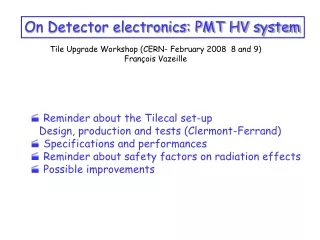
CAN BUS ELMB CAN TRANSCEIVER 13 GOL 24 SYNC RS232 JTAG TEST FACILITIES I2C EMULATION Board Controller JTAG Controller TTCrx JTAG BUS ECS interface • ECS interface via ELMB card • ATmega128 μprocessor with CAN controller • CANbus lines on the backplane • 1 branch with up to 16 ODE • RS232 serial interface for local access • ELMB on-board connection • Global reset • Startup (programmable) • ECS ( only way to reset TTCrx and GOL after startup) • 2 I2C bus • 24 SYNC • 13 GOL, TTCrx, L0 controller • Configuration, monitor, SYNC histogram read-out • 1 bus JTAG • Boundary scan • CAN transceiver powered by ODE power supply • Optocoupler must be foresee on PC- CAN interface for galvanic isolation 6 Apr. 2006
ODE chips and registers • 24 SYNC chips • 24 registers each (17 configuration, 7 monitor) • 13 GOL chips • 6 registers each (4 configuration, 2 monitor) • 1 TTCrx chips • 20 registers (11 configuration, 9 monitor) • L0 controller • 16 registers (12 configuration, 4 monitor) • 690 registers of 8 bits • Single bit access needed • ~ 430 objects in the CAN dictionary • Board configuration required several (many) registers accesses 6 Apr. 2006
Board configurations • DAQ mode • SYNCs, GOLs, TTCrx, L0 controller configuration registers loaded via ECS • Standard acquisition mode • DAQ-SYNC Test Mode • SYNCs, GOLs, TTCrx, L0 controller configuration registers loaded via ECS • Test DAQ data path • Known patterns loaded in SYNC L0 derandomizer via ECS • “Normal” data readout by board controller • DAQ-Internal Test Mode • GOLs, TTCrx, L0 controller configuration registers loaded via ECS • Test data link integrity and performances • Known patterns loaded in L0 board controller via ECS • 8 bits Pseudo-random sequence • Trigger test mode • SYNCs, GOLs, TTCrx configuration registers loaded via ECS • Test trigger link integrity and performances • Fixed pattern defined via ECS • 8 bits Pseudo-random sequence • Histogram mode • SYNCs configuration registers loaded via ECS • Histogram readable via ECS • DAQ data dump • DAQ GOL frame dumped in a internal FIFO • DUMP mode programmable and readable via ECS • All TTCrx signals emulated via ECS (L0_YES, BC_res, EV_res, L0_res) • NO L0_YES needed in test mode 6 Apr. 2006
ELMB firmware • Final ELMB firmware released • Bridge between CAN (RS232) interface and internal bus (I2C, JTag) • CANopen CiA DS-301 standard, limited to the so called Predefinited-Connection-Set but including the SDO Block Download/Upload protocols, and a semi-standard mechanism for Multiple PDO transmission protocol • implementation of an Object-Dictionary with more than 430 objects fully accessible • “Standard” ELMB Firmware partially re-written (SEU compliance) for • Optimization of data transfer speed • Multiple PDO implemented (data transfer without protocol overhead) • Local configuration procedures • Single CAN command for board configuration • Default setting • Histogram and dump FIFO download • Parallel internal access to minimize dead time • Use of internal EEPROM for data storage; • Implementation of the In-System-Programming, via Bootloader firmware, for the program-code renewing of the ELMB processor 6 Apr. 2006
Test program • Serial interface for local access • RS232 • Program on ELMB flash ram • Shell for command decoding 6 Apr. 2006
Test program • ODE tester program • Win32 application (visual basic + DLL in C language) • Management and work-benching of a ODE crate via CAN bus • Bus traffic monitor (detailed information for each intercepted message) • Node status monitor and control via Network-Management (NMT) facility • Scripting language console for high level command • CAN-JTag command translator (to be implemented) • Tool panels for • Object-Dictionary access in reading and writing; • CANopen Error-Control-Protocols management: Node-guarding/Heartbeat, Life-guarding; • In-System-Programming; • SYNC chips histogram downloading and graphing; • ODE test procedures; • configuration and default parameters storing/retrieving; • etc... (?) 6 Apr. 2006
ODE framework • Working in progress … • Translate some ODE tester functionalities in PVSS script but: • ODE is an “optical” board, therefore its output required an “optical” receiver (TELL1 and Trigger board) to be controlled at he same time • Some procedures (alignment, pulsing, …) required a contemporary control of other boards (Service Board, Dialog, …) • What the global experiment ECS want from us … • What can be useful for the Muon detector for monitoring and debug … • Manpower required and time schedule … • Only 1 person involved in LNF (perhaps not enough) 6 Apr. 2006