Download
1 / 39
390 likes | 444 Vues
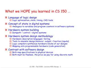
This lecture covers the implementation of sequential networks, including Midterm Reflection responses and grading policy. It also discusses base number systems, function equivalence, Boolean algebra, and flip-flops design in detail. The instructor's advocacy for fair and reasonable grading policies is highlighted.

E N D
W’05 CS M51A/EE M16 Winter’05 Section 1 Logic Design of Digital SystemsLecture 12 February 28 Yutao He yutao@cs.ucla.edu 4532B Boelter Hall http://courseweb.seas.ucla.edu/classView.php?term=05W&srs=187154200
Outline • Midterm Reflection • Review - Spec of Sequential Systems • Chapter 8 • Implementation of Sequential networks
Midterm Reflection • Responses: • “Fair, reasonable but a bit long” • “Didn’t spend too time on arithmetic due to overwhelming load” • “BILL Gates really gave me hard time” • Scaling Formula: • Score = Pi /0.95 + P9 • Grading Policy: • Consistent: Stick to the problem description • Fair: wrong can’t take the same credit as right • Reasonable: typo deserves more credit than conceptual error • Lenient: Brave and sensible trying is given at least one point 8 i = 0
Midterm Statistics Highest: 101.87 Lowest: 26.32 Mean: 73.93 Median: 77.84 7 1
- Positive - Negative Base 10 Number Systems and Conversions Prob. #7 Base 8 Base 16 Prob. #1 Base 2 - Function Equivalence Specification Truth Table Prob. #2,8 K-Map S. E. - Boolean algebra - K-Map Based - Quine-McCluskey Algorithm Minimization Prob. #3, 4 Implementation - Gate networks (Universal Set) + two-level + multiple-level - PLAs AND-OR NAND-NAND Prob. #5, 9 OR-AND NOR-NOR Analysis - Functional Analysis -> Debugging - Delays: H-> L and L->H - Fan-out/Fan-in Prob. #6 Midterm Coverage Anatomy
Arithmetic o o Prob. #6,7 Signed Integer T.C. Form Conversion Positive True Negative Complement Addition Addition (Carry) Subtraction Complementation + Addition Left Right Shift Operation Multiplication Division Overflow . Range Extension . Detection Out of Range Midterm Coverage Anatomy (Cont.)
Midterm: Final Words • If you ask for reviewing your Midterm • Write up your arguments and attach it with your Midterm • Hand it over to me or Ken by March 7 (Monday) • It’s not final yet • If you did well, don’t slack off • If you did poorly, don’t give up • Only the final score counts. • Please let me know your problem and we’ll work it out altogether
Recap - Spec of Sequential Systems • Basic concepts • Synchronous sequential systems • Clocks • States • Finite state machines • Mealy and Moore machines • Basic specification methods • Time behavior (I/O sequence) • State transition table • State diagram • Basic problems • State decision (word problem) • The most difficult and challenging part • Common sense and practice are important
Case Study 3: Controller • A FSM that produces control signals as the states are traversed. • Control signals determine actions performed by other parts of the system. • Two types • Autonomous • State transitions follow a fixed sequence of states, independent of any inputs except the clock. • Non-autonomous • The transition is decided by external inputs
Sequential Networks - Overview • Canonical sequential networks • Basic building blocks for sequential systems • Latches • Flip-flops • D flip-flops • SR flip-flops • JK flip-flops • T flip-flops • Design of flip-flop networks • Analysis of flip-flop networks
Mealy and Moore Machines Mealy Machine Moore Machine
"1" "stored value" "0" "remember" "load" "stored value" "data" Simplest Seq. Circuits with Feedback • Two NOT gates form a static memory cell • Will hold value as long as it has power applied • How to get a new value into the memory cell? • Selectively break feedback path • Load new value into cell
Q R S R Q Q' S Memory with Cross-Coupled Gates • Cross-coupled NOR gates • Similar to NOT gate pair, with capability to force output to 0 (reset=1) or 1 (set=1)
Level-Sensitive (triggered) Gated Latch • Latch: • a sequential device that changes its outputs at any time, independent of a clock signal
Correct Timing Behavior Incorrect Timing Behavior Race Condition Limitations of Gated Latch s(t+1) = s(t) x(t)
Trailing (falling)-edge-trigged (Negative-edge-trigged) Leading(rising)-edge-trigged (Positive-edge-trigged) A Solution: Edge-Trigged Cell
Master-Slave Implementation • Consists of two stages of gated latches • Master and Slave • Input is loaded into the master during the clock pulse • Input is transferred to the slave after the clock pulse
Flip-Flop • A sequential device that samples its inputs & changes its outputs only at times decided by a clock signal. • Four basic types • D flip-flop • SR flip-flop • T flip-flop • JK flip-flop • Four types of flip-flops differ in • number of inputs • excitation equation • characteristic equation • Each state bit is implemented with a flip-flop
D (Delay) Flip-Flop Block Diagram State Diagram Characteristic Equation Excitation Equation
SR(Set/Reset) Flip-Flop Block Diagram State Diagram Characteristic Equation Excitation Equation
T (Toggle) Flip-Flop Block Diagram State Diagram Characteristic Equation Excitation Equation
JK Flip-Flop Block Diagram State Diagram Characteristic Equation Excitation Equation
Design of Sequential Systems Decide: Inputs,Output, States, Function Step 1: Obtain: Formal Specification Step 2: Write: Output Table State Table Draw: State Diagram Step 3: Minimize: States Step 4: Encode: State Assignment Step 5: Implement:
Step 4: State Assignment • Goal: • Represent each state with a bit vector • Basic question to ask: • How many bits are required to represent states? • Encoding schemes: • Binary codes • Other codes: • Gray codes, etc. • How to choose m out of n codes for encoding states?
Step 5: Implementation • Construct a sequential network with specified memory elements and combinational logic • Two types • Canonical implementation • Implementation with flip-flops • For Canonical implementation • Just use state registers (D flip-flops) to store states • For other types of flip-flops • Use the excitation tables
Four 6-input switching functions Example 8.1(Cont’d)
Ex. 8.8 - Modulo-5 Counter • Use T flip-flops to design a modulo-5 counter
5, 6, and 7 are don’t cares! Ex. 8.8 - Modulo-5 Counter (Cont’d) • State Assignment • State Transition Table
x To Be Designed y2 T T T Q Q Q CLK CLK CLK y1 Q Q Q y0 Ex. 8.8 - Modulo-5 Counter (Cont’d) • Truth Tables for T0,T1,T2
Ex. 8.8 - Modulo-5 Counter (Cont’d) • K-Maps • Switching Expressions
Summary • Midterm Recap • Basic building blocks of sequential systems • Gated latches • flip-flops • Design and implementation of sequential systems • Canonical forms • flip-flops
Next Lecture • Wrap-up Chapter 8 • Design with one-hot approach • Analysis of sequential networks • Timing characteristics • Timing analysis • Functional analysis