Download
1 / 2
20 likes | 193 Vues
ESE – Andrew Rusek. Applications of Computer Modeling in Electromagnetic Compatibility (EMC) Tests (Part1). P8 . Field Pattern of Three Radiating Objects (0.6 GHz) All Sources in Phase. Field Pattern of Three Radiating Objects (1.0 GHz)

E N D
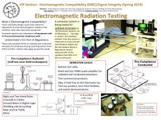
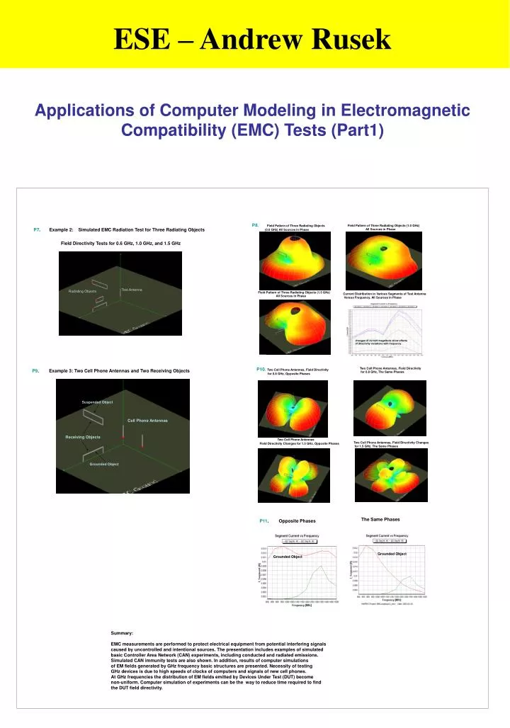
ESE – Andrew Rusek Applications of Computer Modeling in Electromagnetic Compatibility (EMC) Tests (Part1) P8. Field Pattern of Three Radiating Objects (0.6 GHz) All Sources in Phase Field Pattern of Three Radiating Objects (1.0 GHz) All Sources in Phase P7. Example 2: Simulated EMC Radiation Test for Three Radiating Objects Field Directivity Tests for 0.6 GHz, 1.0 GHz, and 1.5 GHz Test Antenna Radiating Objects Field Pattern of Three Radiating Objects (1.5 GHz) All Sources in Phase Current Distribution in Various Segments of Test Antenna Versus Frequency. All Sources in Phase changes of current magnitude show effects of directivity variations with frequency P10. Two Cell Phone Antennas, Field Directivity for 0.8 GHz, Opposite Phases Two Cell Phone Antennas, Field Directivity for 0.8 GHz, The Same Phases P9. Example 3: Two Cell Phone Antennas and Two Receiving Objects Suspended Object Cell Phone Antennas Receiving Objects Two Cell Phone Antennas Field Directivity Changes for 1.5 GHz, Opposite Phases Two Cell Phone Antennas, Field Directivity Changes for 1.5 GHz, The Same Phases Grounded Object The Same Phases P11. Opposite Phases Grounded Object Grounded Object Summary: EMC measurements are performed to protect electrical equipment from potential interfering signals caused by uncontrolled and intentional sources. The presentation includes examples of simulated basic Controller Area Network (CAN) experiments, including conducted and radiated emissions. Simulated CAN immunity tests are also shown. In addition, results of computer simulations of EM fields generated by GHz frequency basic structures are presented. Necessity of testing GHz devices is due to high speeds of clocks of computers and signals of new cell phones. At GHz frequencies the distribution of EM fields emitted by Devices Under Test (DUT) become non-uniform. Computer simulation of experiments can be the way to reduce time required to find the DUT field directivity.
ESE – Andrew Rusek Applications of Computer Modeling in Electromagnetic Compatibility (EMC) Tests (Part2) P2. Example 1: Transceiver Modeling P1. New Electromagnetic Interference Issues Investigated at OU: GHz frequency range interference and radiating device directivity (necessity of introduction of new EMC standards and measurement methods to recognize device directivity) Simulations helpful to detect peaks of radiation, and prepare experimentation and training Cell phone and other wireless device interference into sensitive medical and automotive systems (Hospitals, Automobiles, etc) GPS and other navigation instrumentation EMC problems PRESENTED: Examples of Modeling Example 1: CISPR (EMC Standards) based conducted and radiated emissions tests; Immunity tests. Controller Area Network (CAN) transceivers are tested (Research completed in cooperation with DaimlerChrysler) Example 2: Simulated GHz range EMC radiation test for three radiating objects to observe field directivity effects Example 3: Example 3: Two Cell Phone Antennas and Two Receiving Objects Model of CAN Transceiver with External Components Mid-Layer Model of CAN Transceiver Common-Mode Filter Structure P3. P4. Conducted and Radiated Emission Test CAN Transceiver Transmitting Pulses CAN Receiver Receiving Pulses Internal Transmitter Model Twisted Pair Cable Antenna Model for CISPR 25 Radiated Emission Tests Developed by Mr. W. Hall, DaimlerChrysler Internal Receiver Model P6. Simulated Immunity Tests P5. Measured Conducted Emissions Max. freq = 5 MHz Simulated Conducted Emissions Interference Generator Measured Conducted Emissions MHz Interfering Signals Simulated Radiated Emissions Measured Conducted Emissions Max. freq. = 50 MHz Transmitted Signal Received Signal Interrupted Communication OK signals