Download
1 / 62
650 likes | 999 Vues
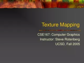
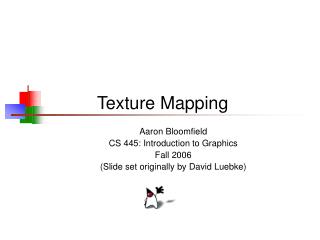
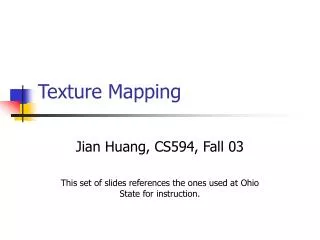
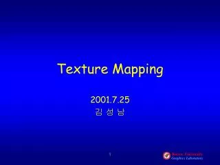
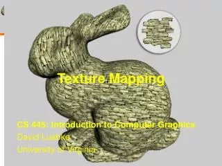
Texture Mapping. Typical application: mapping images on geometry. =. +. RGB texture 2D (color-map). 3D geometry (quads mesh). More examples. Texture Mapping. The fragment operations can access a specialized RAM The Texture RAM Organized in a set of Textures

E N D
Typical application: mapping images on geometry = + RGB texture 2D (color-map) 3D geometry (quads mesh)
Texture Mapping • The fragment operations can access a specialized RAM • The Texture RAM • Organized in a set of Textures • Each texture is an array 1D, 2D o 3D of Texels (texture elements) of the same type
Texels • Typical examples of texels: • each texel is a color (components: R-G-B, or R-G-B-A) • The texture is a "color-map" • each texel is an alpha value • the texture is an "alpha-map" • each texel is a normal (components: X-Y-Z) • the texture is a "normal-map" or "bump-map" • each texel contains a specularity value • the texture is a "shininess-map" • ...
More examples + =
Ed Catmull (MEGA-MEGA-GURU) Texture Mapping: History • 1974 introduced by Ed Catmull • In its Phd Thesis • Only in 1992 (!) we have texture mapping hardware • Silicon Graphics RealityEngine • 1992 on: increasingly used and integrated in graphic cards • First of all by low end graphic boards • Today: a fundamental rendering primitive • the main image-based technique
v 1.0 512 texels u 1.0 1024 texels texel Notation Texture Space (or "parametric space" or "u-v space") Texture 2D A Texture is defined In the region [0,1] x [0,1] of the "parametric space"
v u1,v1 u0,v0 u1,v1 Position of the 1st vertex Attributes of the 1st vertex u0,v0 u2,v2 u2,v2 u Texture Space Texture Mapping • We associate to each vertex (of each triangle) its u,v coordinates in the texture space x1,y1 x0,y0 x2,y2 Screen Space
Texture Mapping • More precisely, we define a mapping between the 3D triangle 3D and a texture triangle Screen Space Texture Space
texture look-up Texture Mapping • each fragment has its own u,v coordinatesin the texture space Screen Space Texture Space
texturelook-up including: texture coordinates (per vertex!) interpolation texture coordinates texture coordinatesinterpolated Texture Mapping set-up points rasterizer Projected Vertices & computed attributes Fragments & interpolated attributes Vertices & their attributes Screen buffer set-up Triangles rasterizer vertexcomputation Fragment computations set-up Segments rasterizer Texture RAM
Problem: linear interpolation of texture coordinates • Not true for perspective projection! • It is only an approximation • It works fine to interpolate colors, normals, .. • Not applicable to interpolate texture coordinates... f( v3 ) V3 f( v2 ) projection f f(p) p V2 f( v1 ) V1 f(p) has barycentric coordinates a,b,c in the triangle f(v1)f(v2) f(v3) p has barycentric coordinates a,b,c In the triangle v1v2v3
v 1 u 1 u,v= (1,0) u1,v1= (1,1) u1,v1= (0,0) u1,v1= (0,1) Problem: linear interpolation of texture coordinates • Example:
Problem: linear interpolation of texture coordinates • Example:
A1,B1... A0,B0... p A2,B2... Solution: Perspective Correction • p has barycentric coordinates c0 c1 c2 p =c0 v0 +c1v1+c2v2 V1 V0 = ( x0, y0, z0, w0) Attributes of p: (not considering the “perspective correction") V2 Ap=c0 A0 +c1A1+c2A2 Bp=c0 B0 +c1B1+c2B2
A1,B1... A0,B0... A2,B2... Solution: Perspective Correction • p has barycentric coordinates c0 c1 c2 p =c0 v0 +c1v1+c2v2 Attributes of p: (not considering the “perspective correction") V1 V0 = ( x0, y0, z0, w0) p V2 A0 A1 A2 Ap =c0 A0+c1A1+c2A2 w0 w1 w2 Ap= w0 w1 w2 1 1 1 Ap =c0 A0+c1A1+c2A2
Solution: Perspective Correction set-up points rasterizer Screen buffer Projected Vertices & computed attributes Fragments & interpolated attributes Vertices & their attributes set-up Triangles rasterizer vertexcomputation Fragment computations set-up Segments rasterizer interpolate A'and w' Final fragment attribute: A'/w' Apply transformations compute: A' = A / w and w' = 1 / w A0 Original attribute A A1 A2 c0 +c1+c2 w0 w1 w2 Ap= 1 1 1 c0 +c1+c2 w0 w1 w2
Perspective Correction • Without With
Perspective Correction • Texture mapping with perspective correction • Also known as Perfect texture mapping
L O A D Texture RAM Note: the texture must be loaded set-up points rasterizer Screen buffer Projected Vertices & computed attributes Fragments & interpolated attributes Vertices & their attributes set-up Triangles rasterizer vertexcomputation Fragment computations set-up Segments rasterizer
Note: the texture must be loaded • From hard disk to main RAM memory • (in the motherboard) • From main RAM memory to Texture RAM • (on board of the graphics HW) Both steps are quite slow. It is not possible to accomplish them once per frame!
In OpenGL glEnable(GL_TEXTURE_2D); glBindTexture (GL_TEXTURE_2D, ID); glTexImage2D ( GL_TEXTURE_2D, 0, // mipmapping GL_RGB, // original format imageWidth, imageHeight, 0, // border GL_RGB, // RAM format GL_UNSIGNED_BYTE, imageData); • As an example:
texturelook-up including: coordinatestexture (per vertex!) including: texture coordinates (per vertex!) interpolation texture coordinates Interpolated texture coordinates Assigning texture coordinates to vertices set-up points rasterizer Screen buffer Projected Vertices & computed attributes Fragments & interpolated attributes Vertices & their attributes set-up Triangles rasterizer vertexcomputation Fragment computations set-up Segments rasterizer Texture RAM
Assigning texture coordinates to vertices • 2 possibilities: • Computing textures coordinates on the fly • During the rendering… • Precomputing • (and store them within the mesh) The choice is application-dependent!
Difficult problem: u-v mapping • Associate texture coordinates to each vertex of the mesh • During preprocessing v v u u
Difficult problem: u-v mapping Hand-made or automated
In OpenGL • Like any other attribute TexCoord2d( u,v )
texturelook-up interpolating texture coordinates texture coordinates interpolated Assigning texture coordinates to vertices set-up points rasterizer Screen buffer Projected Vertices & computed attributes Fragments & interpolated attributes Vertices & their attributes set-up Triangles rasterizer vertexcomputation Fragment computations set-up Segments rasterizer texture coordinates (transformed) including: texture coordinates Texture RAM
Assigning texture coordinates to vertices • 2 possibilities: • Computing textures coordinates on the fly • During the rendering… • Precomputing • (and store them within the mesh)
texturelook-up Interpolated texture coordinates interpolating texture coordinates Assigning texture coordinates to vertices set-up points rasterizer Screen buffer Projected Vertices & computed attributes Fragments & interpolated attributes Vertices & their attributes set-up Triangles rasterizer vertexcomputation Fragment computations set-up Segments rasterizer compute texture coordinates Using the position texture coordinates Texture RAM
Automatically computed • Idea: from (x,y,z) to (u,v) - Linearly • Using object or view coordinate • (before or after the trasformation) • Examples:
1D texture! Automatically computed • Even 1D
Assigning texture coordinates to vertices • 2 possibilities: • Computing textures coordinates on the fly • During the rendering… • Precomputing • (and store them within the mesh)
Environment mapping: spherical Environment map: a texture containing the color of the environment “reflexed by each normal of the half-sphere”. The texture coordinate is the transformed normal!
Simulates a mirror-like object reflecting a far-away background simulates a complex material (fixed lighting) Environment mapping: spherical
Environment mapping: cube above left front right back below
interpolating 3D texture coordinates interpolated coordinates 3D texture Environment mapping: cube set-up points rasterizer Projected Vertices & computed attributes Fragments & interpolated attributes Vertices & their attributes set-up Triangles rasterizer vertexcomputation Fragment computations Screen buffer set-up Segments rasterizer Project on the cube, look-up the corresponding face compute 3D Texture coordinates [-1,+1] x [-1,+1] x [-1,+1] As view ray reflexed by the normal Texture RAM
Environment mapping: cube above left front right back below
Environment mapping: cube and spherical • Spherical: • one texel for each direction in the half-sphere • Projected on a circle • the texture coordinate is the normal • It has the "headlight“ effect: • I can only rotate the object while the viewpoint does not change • Cube • one texel for each direction in the sphere • Projected on the surface of the cube • the texture coordinate is the view direction reflexed by the normal • The viewpoint can rotate around a steady object
Automated computation of texture coordinates S, T, R, Q 1- abilitate: glEnable(GL_TEXTURE_GEN_S); 2- choice of the mode: glTexGeni(GL_S , GL_TEXTURE_GEN_MODE , mode ) Computes the texture coordinates from the position in object coordinates (before the trasformation) GL_OBJECT_LINEAR GL_EYE_LINEAR GL_SPHERE_MAP Computes the texture coordinates from the position in view coordinates (after the MODEL-VIEW) = mode The texture coordinates is the reflexed view ray (using the normal) (after the MODEL-VIEW)
Automated computation of texture coordinates 3- choice of the plane S, T, R, Q glTexGenfv(GL_S, GL_EYE_PLANE , v); or EYE OBJECT 4 elements vector The resulting texture coordinate = vT• pos_vertex (It’s the distance from the plane!)
Texture Look-up out of bounds: “clamp” mode v 1 u 1 if (u<0) u←0; if (u>1) u←1; if (v<0) v←0; if (v>1) v←1;
u ← u – [ u ] v ← v – [ v ] Texture Look-up out of bounds: “repeat” mode v 1 u 1
Repeated textures • Typical use: Note: the texture must be TILEABLE Very space-efficient!
note: u and v treated separately example: repeat u and clamp v In OpenGL Texture parameters. each texture loaded in memory has its own parameters. glTexParameteri( GL_TEXTURE_2D, GL_TEXTURE_WRAP_S, GL_CLAMP ); or glTexParameteri( GL_TEXTURE_2D, GL_TEXTURE_WRAP_S, GL_REPEAT );
texture look-up Texture Look-up • A fragment can have non-integer coordinates (in texels) Screen Space Texture Space
texel pixel magnification pixel minification Texture Look-up one pixel = less than one texel Screen Space Texture Space one pixel = more than one texel
7.5 6.5 5.5 4.5 3.5 2.5 1.5 0.5 0.5 1.5 3.5 4.5 5.5 6.5 2.5 Magnification v Solution 1: Use the texel containg the pixel (that is, the texel whose center is closest to the u,v coordinates of the fragment) Equivalent to rounding up the texel coordinates to the nearest integer "Nearest Filtering" 7.5 u
"texels are visible !" Magnification Nearest Filtering: result texture 128x128