Download
1 / 1
10 likes | 111 Vues
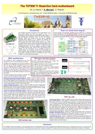
VFAT ROC Data GOH. 0….…………………………..…15. VFAT 0. 192………………………………………………….………………………………..…….…………………………………...…..………………...………………0. VFAT 0. CRC16 checksum <0:15>. CRC16 checksum <0:15>. CRC16 checksum <0:15>. CRC16 checksum <0:15>. Channel Data <0:127>. Channel Data <0:127>.

E N D
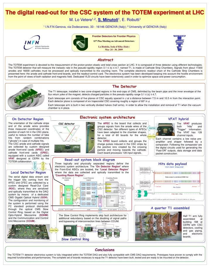
VFAT ROC Data GOH 0….…………………………..…15 VFAT 0 192………………………………………………….………………………………..…….…………………………………...…..………………...………………0 VFAT 0 CRC16 checksum <0:15> CRC16 checksum <0:15> CRC16 checksum <0:15> CRC16 checksum <0:15> Channel Data <0:127> Channel Data <0:127> Channel Data <0:127> Channel Data <0:127> . . . . . . . . . y 176.………………….……..…..192 u Data output is serialized MSB first …………..……………..… v 0….…………………………..…15 VFAT 15 VFAT 15 last word first word One Packet 176.………………….………....192 1010 1010 BC <11:0> BC <11:0> BC<0:11> BC<0:11> BC<0:11> BC<0:11> 010 1 010 1 010 1 010 1 1100 1100 EC <7:0> EC <7:0> Flags <3:0> Flags <3:0> Flags<0:3> Flags<0:3> Flags<0:3> Flags<0:3> EC<0:7> EC<0:7> EC<0:7> EC<0:7> 0011 0011 0011 0011 1110 1110 ChipID <11:0> ChipID <11:0> ChipID<0:11> ChipID<0:11> ChipID<0:11> ChipID<0:11> 0111 0111 0111 0111 DAta Valid = 4.8s Channel Data <127:0> Channel Data <127:0> Frontier Detectors for Frontier Physics CRC16 checksum <15:0> CRC16 checksum <15:0> VFAT 192 serial bits 16VFATs per GOH 12GOHs per OptoRX and S-Link modules 192x16x12=36864 bits ~4kB packet 11th Pisa Meeting on Advanced Detectors La Biodola, Isola d'Elba (Italy)May 24 - 30, 2009 Abstract The TOTEM experiment is devoted to the measurement of the proton-proton elastic and total cross section at LHC. It is composed of three detector using different technologies. The TOTEM detector that will measure the inelastic rate in the pseudo-rapidity region 3.1 ≤ |η| ≤ 4.7, named T1, is made of Cathode Strip Chambers. Signals from about 11000 anodes and 16000 cathodes must be processed and optically transmitted to the counting room. The complete electronic readout chain of the Cathode Strip Chambers is presented here: the anode and cathode front-end boards, and the readout-control card. The electronics system has been developed keeping into account the hostile environment from the point of views of both radiation and magnetic field. Dedicated VLSI circuits have been extensively used in order to optimize space and power consumption. The Detector The T1 telescope, installed in two cone-shaped regions in the end-caps of CMS, delimited by the beam pipe and the inner envelope of the flux return yoke of the magnet, detects charged particles in the pseudo-rapidity range 3.1 ≤ |η| ≤ 4.7. Each telescope arm consists of five planes of CSC equally spaced in z at a distance between 7.5 m and 10.5 m from the interaction point. Each detector plane is composed of six trapezoidal CSC covering roughly a region of 60º in . Each telescope arm is built in two vertically divided halves (half arms), in order to allow the installation and removal of T1 when the vacuum chamber is in place. On Detector Region The AFEC is the board that collects and groups signals from the anode wires of the CSC detector. Ten different types of AFECs have been adapted to the chamber shapes, for a total of 60 boards for the whole detector. The CFEC board collects and groups the charge pulses induced in the CSC strips by the positive ions created by the crossing particle and moving towards the cathode. Each board processes 128 input signals. CSC detector AFEC CFEC Read-out system block diagram Three logically and physically separated regions define the electronic system architecture. The “On Detector Region” where the Front-End ASICs are located, the “Local Detector Region” where the data are collected and optically transmitted to the “Counting Room Region”. Hits data payload A quarter T1 assembled Half T1 arm fully assembled at building 188 at CERN with CSC detectors, cooling and gas piping, and electronic boards. The Slow Control Ring implements skip fault architecture for additional redundancy based on the doubling of signal paths and bypassing of interconnection lines between CCUM. Slow Control Ring The digital read-out for the CSC system of the TOTEM experiment at LHC M. Lo Vetere1,2, S.Minutoli1, E. Robutti1 1 I.N.F.N Genova, via Dodecaneso, 33 - 16146 GENOVA (Italy); 2 University of GENOVA (Italy) Electronic system architecture VFAT hybrid The orientation of the cathode strips and of the anode wires provides three measured coordinates of the position of each hit in the CSC plane, useful to reduce the number of fake hits from random combinations (“ghosts”) in case of multiple hits. The CSC anode and cathode signals are collected by custom designed anode front-end cards (AFEC) and cathode front-end cards (CFEC), equipped with a custom ASIC called VFAT designed at CERN by the TOTEM collaboration. The VFAT produces both “Hits” and “Trigger” information. The VFAT has 128 channel inputs. Data Path Control Path Each channel contains a low noise pre-amplifier and shaper followed by a comparator. Following the comparator are the digital circuits used for generating the “Fast-OR” outputs, data storage and data packet construction. Control Path Data Path Local Detector Region The serial digital data stream and the trigger bits coming from the AFEC and CFEC are collected by a custom designed Read-Out Card (ROC), where they are serialized and optically transmitted to the DAQ system by means of a dedicated CMS Gigabit Optical Hybrid (GOH). The configuration and monitoring of the system is performed using the I2C standard protocol distributed through the optical CMS Slow Control Ring, based on the Digital Opto-Hybrid Mezzanine (DOHM) and the Communication and Control Unit Mezzanine (CCUM). Control Path ROC Conclusions The TOTEM T1 detector electronics system is fully integrated within the TOTEM DAQ and also fully compatible with CMS DAQ requirements. Prototypes have proven to comply with the required functionalities and performances. The complete set of boards necessary to equip the T1 detector have been built, tested and are ready to be mounted on the detector.