Download

1 / 18
210 likes | 376 Vues
EET 503 Power System Protection (Instrument transformer ). Instrument Transformer. There are two basic types of instrument transformer: voltage transformers (VTs), formerly called potential transformer (PTs), and current transformers (CTs). Instrument Transformer.

E N D
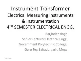
EET 503 Power System Protection (Instrument transformer )
Instrument Transformer There are two basic types of instrument transformer: voltage transformers (VTs), formerly called potential transformer (PTs), and current transformers (CTs)
Instrument Transformer For system-protection purpose, VTs are generally considered to be sufficiently accurate. Therefore, the VT is usually modeled as an ideal transformer, where, Standard VT ratios are given by Table below
Instrument Transformer Ideally, the VT secondary is connected to a voltage-sensing device with infinite impedance, such that the entire VT secondary voltage is across the sensing device. Ideally, the CT secondary is connected to a current sensing device with zero impedance, such that the entire CT secondary current flows through the sensing device.
Instrument Transformer Standard CT ratios are given in Table below.
Instrument Transformer An approximation equivalent circuit of a CT is shown in figure below Where Z’ = CT secondary leakage impedance Xe= (saturable) CT excitation reactance ZB= Impedance of terminating device (relay, including loads)
Instrument Transformer The total impedance ZB of the terminating device is called the burden and is typical expressed in value of less than an ohm. The CT equivalent circuit is an excitation curve that determines the relationship between the CT secondary voltage E’ and excitation current Ie. Excitation curves for a multiratio bushing CT with ANSI classification C100 are shown in figure below.
Instrument Transformer Current transformer performance is based on the ability to deliver a secondary output current I’ that accurately reproduces the primary current I. Performance is determined by the highest current that can be reproduced without saturation to cause large error.
Instrument Transformer Using the CT equivalent circuit and excitation curves, the following procedure can be used to determine CT performance. STEP 1 Assume a CT secondary output current I’ STEP 2 Compute E’= (Z’ + ZB) I’ STEP 3 Using E’, find Ie from the excitation curve. STEP 4 Compute I=n (I’ + Ie) STEP 5 Repeat Step 1-4 for different values of I’, then plot I’ versus I.
Instrument Transformer The CT error is the percentage difference between (I’+Ie) and I’, given by
Instrument Transformer Example 1
Instrument Transformer Example 2: