Download
1 / 16
160 likes | 313 Vues
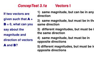
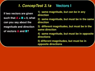
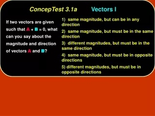
Stress in any direction. s y. t xy. Y. F 4. Y. F 3. F n. X. F 2. F 1. Z. X. Z. Two dimensional state of stress and stress element. Y. s y. t xy. t xy. s x. s x. t xy. t xy. s x. t xy. s x. t xy. t xy. X. s y. s y.

E N D
sy txy Y F4 Y F3 Fn X F2 F1 Z X Z Two dimensional state of stress and stress element Y sy txy txy sx sx txy txy sx txy sx txy txy X sy sy If a body is subjected by external forces F1, F2, ….Fn, all acting on a plane parallel to XY plane, then stress will be developed inside the elastic body. The stress at an arbitrary point within the body can be described by drawing an microscopic cubicstress element (dx, dy, dz) aligned to an XYZ coordinate system around the point and determining the normal and shear stresses on each face of the cube. If the external forces are co-planer and parallel to XY plane, the state of stress can be completely defined by: sx = normal stress in X direction, sy = normal stress in Y direction, and txy = shear stress which would be equal in magnitude X and Y direction
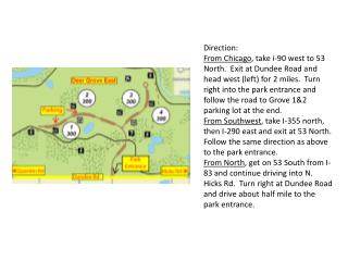
Previously, we have learnt how to calculate normal (sx & sy) and shear (txy) stresses in different types of loading conditions (axial, bending and torsion). sy Y txy For example, for a bending load on a simply-supported beam, we know the stress condition at the point shown, can be calculated from the formulas such as, sx= Mv/I+P/A, sy = 0, and txy=VQ/(Ib). txy sx txy sx X txy Y F1 sy F2 X Note that these formulas calculate stresses parallel to X and Y axis, which is predefined by the geometry of the part.
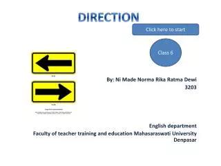
sy Y v v txy tuv sv tuv txy su sx f txy sx tuv X su F txy tuv f Y Y F sv sy v u X f u u X X Now, knowing the stress condition at a point along XY coordinate system, we want to determine the stress condition for the same point, along a new coordinate system, which is rotated by an arbitrary angle f ie., given sx, sy, txy and f, find su, sv, tuv
f sy sy(LBsinf) sy Y txy Lsinf txy(LBcosf) txy(LBsinf) txy txy Lcosf f f f L tuv tuv(LB) txy sx su sx sx(LBcosf) txy sx su(LB) X txy sy 2. To maintain the equilibrium of the cut piece, let the normal and shear stresses in the cut plane su & tuv, respectively are developed. 1. Our original stress element is cut by an arbitrary plane at an angle f 4. Assuming the thickness of the element is B, then forces on each side of the cut element are stress multiplied by the area of the face. 3. Let, L be the length of the cut side. Then the other two sides are Lsinf & Lcosf
syLBsinfcosf syLBsin2f f sxLBcos2f txyLBsinfcosf f sy(LBsinf) txyLBsin2f sxLBcosfsinf txy(LBcosf) txy(LBsinf) txyLBcos2f tuv(LB) f tuv(LB) f f sx(LBcosf) txyLBsinfcosf su(LB) su(LB) f 5. Forces acting on the cut element 6. Resolving the forces in u & v directions Equating forces in u-direction: suLB = sxLBcos2f+ syLBsin2f + 2txyLBsinfcosf Or, su = sxcos2f + sysin2f + 2txysinfcosf ………..(1) Equating forces in v-direction: tuvLB = txyLBcos2f - txyLBsin2f - sxLBsinfcosf+ syLBsinfcosf Or, tuv = txy(cos2f - sin2f) – (sx-sy)sinfcosf ……. (2)
Replacing the square terms of trigonometric functions by double angle terms and rearranging the equations: Thus knowing a stress condition (sx, sy & txy) at a point in a given orthogonal axis system (xy), we can use equations 3, 4 & 5 to determine stress condition (su, sv & tuv) at the same point along a new axis system (uv) which is rotated by an angle f.Since both set of stresses refer to the same point, the two sets of stresses are also equivalent.
Y sy txy sx X sx f txy sy U These relationships between the stresses in different axis system can be conveniently depicted by Mohr’s circle. Sign convention for Mohr Circle: Normal stress: Tensile = positive Shear stress: Producing clockwise rotation of the element= positive Angle: Clockwise from positive X axis is positive. For the stress element shown: Normal and shear stresses in X-direction are (sx & txy) Normal and shear stresses in Y-direction are (sy,-txy) Since the pair of txy in Y-direction producing CCW rotation so txy is negative for Y-direction. The angle f of direction U is positive.
Y V sy sv txy tuv X X su sx sx f su txy U tuv sy sv • CONSTRUCTION OF MOHR’S CIRCLE FOR A GIVEN STRESS ELEMENT • The axis system of Mohr circle is s-t axis. Draw the s-t axis and name them. • Plot the point X with a coordinate sx and txy along the s-t coordinate system. • Mark another point Y with the coordinate sy and –txy • Join the XY line. Let at point C, XY intersects the horizontal axis. The point C denotes the average normal stress. The line CX denotes X axis and line CY denotes Yaxis in mohr circle. • Note CX and CY are making 1800 angle with each other, whereas in reality the X and Y axes are at an angle 900. • RULE: ALL ANGLES IN MOHR’S CIRCLE IS TWICE THE REAL ANGLE. • Use C as the center, and draw a circle with XY as the diameter. • To find stress in a direction U-V, which is f angle CW from X-Y axis, draw a line UV through C at an angle 2f CW from XY line. • The coordinate values of U & V denote the normal and shear stress in UV direction. Shearstressaxis (t) su X (sx,txy) U (su,tuv) X axis txy sx sy 2f tuv -s C Normal stress axis (s) tuv Y axis txy V (sv,txy) sv Y(sy,-txy) savg=(sx+sy)/2
PROOF U (su,tuv) Shearstressaxis (t) X axis txy sx sy 2f -s 2q Normal Stress axis (s) a Y axis V (sv,txy) Y(sy,txy) savg=(sx+sy)/2 Y V sy sv txy tuv X X su sx sx f su txy U tuv sy sv X (sx,txy) X
Principal Normal Stresses: s1 & s2 & Maximum Shear Stress: tmax
Similarly if we measure stress at an angle 2f from XY axes, then we get the maximum shear stress tmax Y (savg,tmax) tmax sy txy If we measure the stress at an angle 2q from XY axes, then the normal stress will maximize, and no shear stress will be present. Normal stresses s1 and s2 are called principal normal stresses. X sx sx X (sx,txy) txy X axis txy 2f sy sy 2q sx -s savg o s2 s1 Y s2 txy Y axis Y(sy,-txy) s2 s1 X (savg,-tmax) q -t s1 s1 s2 In design, often we want to know the max normal (s1) and max shear (tmax) stresses to predict failure of a part. Y tmin savg tmax tmax savg f x tmax savg savg
Mohr Circle Example
Finding Principal Normal Stresses (s1 & s2) and Max Shear Stress (tmax) R=13K t Y (8k,13k) 4,000 psi tmax X 20,000 psi X (20k,5k) 20,000 psi X axis 5,000 psi 5k 2f=67.4 o 4,000 psi 2q=22.6 -s 20k s 4k s2=-5k 8k s1=21k Y s2 5k Y axis 5k Y(-4k,-5k) X 21k q=11.3 -t (8k,-13k) 21k s1 5k Y tmin 8k tmax 13k 33.7 x 8k 13k 8k 8k
The end of show and thanks for viewing it