Download
1 / 13

E N D
Structural STRUCTURAL
STRUCTURAL INTRODUCTION The proposed cricket stadium is located in Providence, Guyana and shall be constructed as per the ICC norms for the World Cup to be held in 2007. The stadium of 15,000 capacity is to be constructed under the Ministry of Public Works and Communications with a grant from the Govt of India. This design basis report is drawn only for the structural design of the works in the stadium complex project. As listed in the Architectural basis, there are various buildings in the complex, which serves the requirement for the intended capacity. The report tends to highlight the general design philosophy adopted in the structural design of the elements and also gives an overview of the basis of structural analysis and design adopted to arrive at the estimate. The report also highlights the various methods and loads assessed for the purpose of structural design of elements. It also brings out the reason for adopting various principles chosen for design and gives a comprehensive list of the codal provisions chosen. At the end the list of codes adopted for design is furnished. All materials shall be as per the Indian standards and design shall comply with BS standards as listed below. The Indian Standards are also listed for clarity. Structural
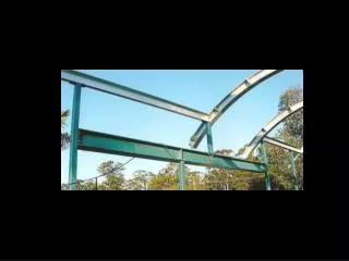
DESIGN PHILOSOPHY The main buildings in the stadium complex are the stands, members and player's pavilion block, venue operating centre, media centre and landscaped seating stand apart from service buildings and underground structures. The structural system adopted for the buildings are concrete/structural steel framed conventional beam slab and column structures on pile caps over bored cast-in-situ concrete piles/pre-cast concrete piles/green heart timber piles. The slabs are proposed in composite construction with concrete on profiled metal decking (serving as reinforcement). The stands are designed with pre-cast bleachers on raker beams in concrete/structural steel. The roof covering the stands are designed with structural steel elements in profiled sections to match the architectural form. The columns in cast-in-situ concrete/structural steel have insert plates/base plates to seat the roof-supporting member. The structures are analysed for dead load, live load and wind loads as per the codal provisions. Waterproofing on concrete surfaces exposed to atmosphere is done with reinforced modified bituminous membrane and is protected by cement concrete tiles. The waterproofing of sunken slabs in toilets is also achieved with the same material. All structural steel surfaces are protected from corrosion with anti-corrosive paint. DESIGN LOADS Dead Loads The self weight of the various elements are computed based on the unit weight of materials as given below: Structural
Imposed Loads As per BS:6399 (Part 1)-1996 the building is classified as Public Assembly building. The superimposed loads or otherwise live load is assessed based on the occupancy classification as per BS:6399(Part 1)-1996 for assembly building. The imposed loads (in kN/m2) considered are as listed below: Structural On flat roofs, sloping roofs and curved roofs with slopes up to and including 10 degrees, the imposed loads due to use or occupancy of the buildings and the geometry of the roofs are given below: As per cl 6.2, BS:6399 (Part 1)-1996 a) For roofs with access provision 1.5 b) For roofs without access provision 0.75
On sloping roof of slope greater than 10o, as per clause 6.3 of BS:6399(Part1)-1996 the imposed loads (kN/m2 of the plan area) that are likely to act permanently are as follows: • Waterproofing* 1.5 (On roof / terrace) • Partitions 1.0 (wherever applicable) • False ceiling 0.5 wherever applicable) • Structural slab shall be sloped suitably to avoid achieving requisite slopes with screed/brick bat coba • Bleachers are designed to resist a horizontal force applied to seats of 3.0 kN per linear meter along the line of seats and 1.5 kN per linear meter perpendicular to the line of seats. • Wind Load • The wind pressure is calculated based on the data furnished below and as per the provisions laid in BS:6399 (Part 2)-1997 • Basic Wind speed = 50m/sec (As assessed from UBC) • Maximum gust = 30mph (13.5m/sec) As given • Mean probable = 50 years • DESIGN LIFE OF STRUCTURE • Building Type factor Kb = 1.0 • Ground roughness category = town • Built up areas with an average level of roof tops at least Ho =5m above GL • Dynamic Augmentation Factor Cr =0.03 Structural
Static Simplified method is used for design for wind loads with the following parameters as per cl 2.2 BS:6399 (Part2)-1997 • Directional Factor Sd = 1.0 • Altitude Factor Sa= 1.0 • Seasonal Factor Ss= 1.0 • Probability Factor Sp = 1.0 • Site Wind Speed Vs = Vb x Sa x Sd x Ss x Sp = 50 x 1 x 1 x 1 x 1 x 1 = 50m/sec • Effective Wind Speed = Vs x Sb • Where Sb is the terrain and building factor obtained from cl 2.2.3.3 of BS:6399(Part2)-1997 • Earthquake Load • Guyana is not within the earthquake belts and also does not figure in the places listed in the seismological active zones. It has been mentioned that Guyana experiences tremors every 5-10 years. Earthquake loads are not considered for analysis and design. With the given conditions it is assumed that the wind load on the structure would be sufficient for the lateral loads that would be generated during the tremors. Structural
Load Combinations Primary loads are combined in accordance with relevant stipulations in BS:8110(Part 1)-1997. The combination that produces the most unfavourable effect in the building, foundation or structural member concerned is adopted for design. Structural • **Eartha and Waterb Pressure • 1Dead and Imposed (and earth and water pressure) • 2Dead and Wind (and earth and water pressure) • 3Dead and Imposed and wind (and earth and water pressure • aThe earth pressure is that obtained from BS:8002 including an appropriate mobilisation factor. The more onerous of the two factored conditions should be taken. • bThe value of 1.2 may be used where the maximum credible level of the water can be clearly defined. If this is not feasible, a factor of 1.4 should be used. • cUnplanned excavation in accordance with BS:8002, 3.2.2.2 not included in the calculation. • dUnplanned excavation in accordance with BS:8002, 3.2.2.2 included in the calculation.
ANALYSIS METHOD The analysis of the structure is carried out using the STAAAD Pro-2003. Appropriate loads and its combinations, as per relevant clauses in BS codes as described in this report are chosen for analysis and design. Precast elements are analysed manually for handling, transportation and service stresses. DESIGN LIFE The design life of the structure is considered as 50 years. This requirement is not applicable for replaceable materials. DESIGN METHODOLOGY All structural elements shall be designed according to the Limit State Method as specified in BS:8110 for reinforced concrete elements and BS:5950 for structural steel elements. FOUNDATION As per recommendations of the soil investigation report, only piles are considered as foundations. The various types of piles considered for supporting load-bearing columns/structures are bored cast-in-situ concrete piles, pre-cast concrete piles and green heart timber piles. The vertical capacity of the pre-cast concrete piles of 20m length is 34mT and that of 23m green heart timber piles is 18mT. Structural
CONCRETEThe grade of concrete and type of cement adopted for the various structural Structural REINFORCEMENT For all structural RC elements steel reinforcement used shall be of Fe 415 grade conforming to IS:1786-1985 or equivalent. NOMINAL COVER TO REINFORCEMENT The cover to concrete shall be as per the guidelines laid in cl 3.3 of BS:8110 Part 1-1997. The cover shall also satisfy the requirements of 2h fire rating. DESIGN STANDARDS The relevant Standard codes, as given below, have been followed for structural design