Download

1 / 20
240 likes | 570 Vues
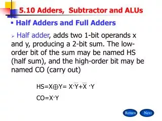
Combined adder and subtractor. 主要内容. 问题描述 设计思想 总体结构 程序描述 测试部分及仿真结果 综合结果 改进方案. 问题描述. 设计一个组合加法减法器,实现六位数与两位数的加和六位数与两位数的减。 加法器和减法器可以用多种方式实现,减法器实现的方式与加法相同, A – B 可以用 A + B 的补码实现。. 设计思想. 考虑本题的功能,用级连加法器实现模拟,级连加法器由 6 个 1 位全加器级连构成,本级的进位输出做为下一级的进位输入。 将两位数 B 扩展成 6 位数,前 4 位为符号位扩展。

E N D
主要内容 • 问题描述 • 设计思想 • 总体结构 • 程序描述 • 测试部分及仿真结果 • 综合结果 • 改进方案
问题描述 • 设计一个组合加法减法器,实现六位数与两位数的加和六位数与两位数的减。 • 加法器和减法器可以用多种方式实现,减法器实现的方式与加法相同,A – B 可以用 A + B的补码实现。
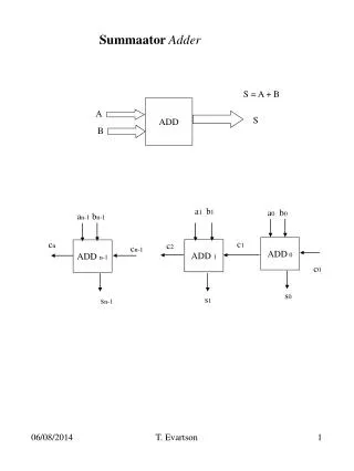
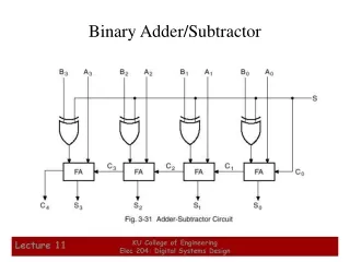
设计思想 • 考虑本题的功能,用级连加法器实现模拟,级连加法器由6个1位全加器级连构成,本级的进位输出做为下一级的进位输入。 • 将两位数B扩展成6位数,前4位为符号位扩展。 • 实现减法时, SUB_ADDBAR置1,减数B的补码用两个XOR门实现,并且用SUB_ADDBAR传递被扩展的符号位,从而实现对B求反加1的功能。 • 实现加法时, SUB_ADDBAR置0,A与B直接相加。 • 当加法上溢和减法下溢时,分别置输出位111111和000000。
Verilog程序描述 • module sixbit_addsub2bit(y,a,b,sub_addbar); • parameter widtha=5; • parameter widthb=1; • output [widtha:0] y; • input [widtha:0] a; • input [widthb:0] b; • input sub_addbar; • integer i; • reg [widtha:0] b_toadd; • wire [widtha:0] carryout; • wire [widtha:0] addout; • reg [widtha:0] y; • always@(sub_addbar or b) • for(i=0;i<widthb+1;i=i+1) • b_toadd[i]=sub_addbar^b[i];
full_add f0 (.a(a[0]),.b(b_toadd[0]),.cin(sub_addbar),.sum(addout[0]),.cout(carryout[0])); • full_add f1 (.a(a[1]),.b(b_toadd[1]),.cin(carryout[0]),.sum(addout[1]),.cout(carryout[1])); • full_add f2 (.a(a[2]),.b(carryout[1]),.cin(sub_addbar),.sum(addout[2]),.cout(carryout[2])); • full_add f3 (.a(a[3]),.b(carryout[2]),.cin(sub_addbar),.sum(addout[3]),.cout(carryout[3])); • full_add f4 (.a(a[4]),.b(carryout[3]),.cin(sub_addbar),.sum(addout[4]),.cout(carryout[4])); • full_add f5 (.a(a[5]),.b(carryout[4]),.cin(sub_addbar),.sum(addout[5]),.cout(carryout[5])); • always@(carryout[widtha] or sub_addbar or addout) • begin: ovr_under_range • if(! sub_addbar && carryout[widtha]) • y=6'b1; • else if (sub_addbar && !carryout[widtha]) • y=6'b0; • else • y=addout; • end • endmodule
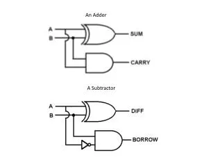
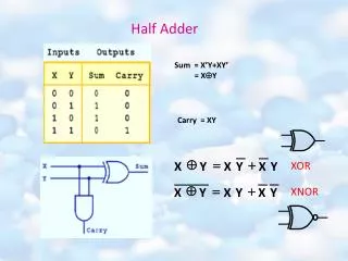
module half_add(a,b,sum,cout) • input a,b; • output sum,cout; • assign sum=a^b; • assign cout=a&b; • endmodule • module full_add(a,b,cin,sum,cout) • input a,b,cin; • output sum,cout; • wire aplusb,coutha1,coutha2; • half_add ha1(.a(a),.b(b),.sum(aplusb),.cout(coutha1)); • half_add ha2(.a(aplusb),.b(cin),.sum(sum),.cout(coutha2)); • assign cout= coutha1|coutha2; • endmodule
Testbench部分代码 • timescale 1ns/1ns • module test; • reg[5:0] a; • reg[1:0] b; • reg sub_addbar; • wire [5:0] y; • parameter DELY=30; • sixbit_addsub2bit ad1(y,a,b,sub_addbar); • initial • begin • #0 a=6'b000000; b=2'b00; sub_addbar=1'b0; • #DELY a=6'b000110; b=2'b01; sub_addbar=1'b0; • #DELY a=6'b001111; b=2'b11; sub_addbar=1'b1; • #DELY $finish; • end • endmodule
仿真结果及波形 • 对以下几组数据进行测试验证模拟电路功能: • A=000110, B=01, 结果000111; • A=001111, B=11, 结果001100 ; • A=000000, B=11, 结果下溢; • A=100000, B=01, 结果上溢;
综合结果 • Software:Synplify pro 5.2 • Technology:Altera MAX9000 • Latency:18ns
结果分析 • 六个一位全加器; • 两个XOR门,两个 AND门,一个OR门; • 一个数据选择器;
存在的问题 问题:本题所用的级连加法器的结构简单,但N位级连加法运算的延时是一位全加器的N倍,延时主要是由于进位信号级连造成的,在需要高性能的设计程序中,这种加法结构不宜采用。
改进方案 1)用并行加法器实现:实现容易,速度快,耗用资源多; 2)用超前进位加法器实现:速度快,资源耗用适度; 3)流水线加法器:加法器整体运行频率提高;