Download
1 / 14
190 likes | 538 Vues
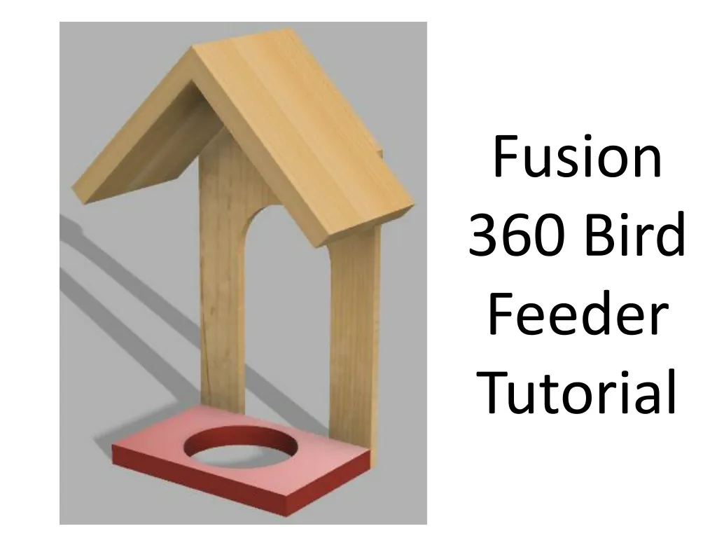
Fusion 360 Bird Feeder Tutorial. Welcome to Fusion 360, lets just quickly take a tour around the workspace.

E N D
Welcome to Fusion 360, lets just quickly take a tour around the workspace. Top left are your general options, you can find any work you have saved previously under top left icon. You can create a new document, save and when you’re working on a model, undo/redo any steps. Top right you can find notifications and messages from users/admin as well as find your account details. If you select your name you can also see the preferences for the program where you can customise the program to your personal style. If you select preferences, the following box will open, select the drawing tab and change the following settings to they replicate the settings in the picture.
2. You will have 3 planes to draw on, depending on your design each one will provide a use, for now we’re going to select the plane between the blue and red axis, it will turn grey when your mouse is over it. 1. Lets get started, we’re going to begin by making the base of our bird feeder. First of all click Sketch and then Create Sketch. 3 orange squares will appear, these are the planes that we can draw on. 3. When you click on the plane, the view will change to a birds eye view of the work space. 4. Select sketch again, then rectangle and then finally center rectangle Click on the middle circle where the red and green lines cross and drag your mouse away from the centre.
6. You can modify dimensions at any time, this can be done by going to sketch, then sketch dimension (2nd option from the bottom) you can click on a side of your shape, drag a dimension bar away from the edge and then click the mouse again, this should allow you to type in a new dimension. 5. Draw out a rectangle that is 80mmx120mm, you can use the mouse to do this or you can manually type in the measurements. 7. Select sketch again, then circle and then finally center diameter circle. Click on the middle circle where the red and green lines cross and drag your mouse away from the centre. 8. Draw out a circle and in the text box type in 64, this will give you a circle with a diameter of 64mm.
9. We’re going to make our shape 3d by extruding it. Click create and then extrude, the camera will change to the original view. 10. Hover your mouse over the space in between the rectangle and the circle, it should turn blue, this means it can be manipulated in some way. Click on it and the box should appear, you can add material thickness by either typing in the thickness or dragging the blue arrow up and down. For now just type in 12. 11. On the top right you have the view cube, you can change the view you see at any point by using this. You can return to its original view by clicking on the home icon. Press ctrl+s to save your work. Save it in a place you can find at any time.
13. This will turn the base from the picture on the left to the picture on the right. 12. We need to turn our base to face a different way. Click on the corner that is highlighted blue. 14. Click on Sketch and create sketch and then click on the face at the front of the base that is highlighted a lighter shade of grey. 15. Once clicked it should take you to the following view: 16. Click on Sketch, rectangle and 2-Point Rectangle. Start from the bottom left corner, draw a rectangle measuring 240mmx120mm. You should have something that looks like this.
18. Create another line on the other side. Length needs to be 100 and angle needs to be 45. 17. Click Sketch and line to select the line tool. Now hover your mouse over the top line in the middle, it should put a cross on the centre of the line and a small triangle, this represents the lines midpoint. Click on this midpoint and drag out to the left and down. Two small textboxes should appear, one is the length of the line and the other is the angle of the line. Length needs to be 100 and angle needs to be 135. 19. Click Sketch and line to select the line tool. Now hover your mouse over the bottom line in the middle, you should see the small cross and triangle again. Click on this midpoint and drag up so that the length of the line is 110mm. Then click on Sketch, circle and center diameter circle. From the end of the 110mm line you have just drew draw a circle with a diameter of 64mm.
20. Using the line tool again draw 2 lines both measuring 110mm like shown below. Remember to start the lines from the bottom line. 21. Notice all this time you have had a Sketch Palette open, we are now going to put this to use. 22. Click on Fix/Unfix and then click on the circle your draw earlier. It should now turn green. Click on Fix/Unfix again to turn the tool off. 23. Now click on the Tangent tool to activate it. Click on the circle you have just fixed and click on the right 110mm line, this should move the straight line so it is tangent to the circle. 24. Do the same with the line on the left so it looks like this.
26. Click Stop Sketch and then click on the blue area to return to a 3D view. 25. Click on sketch and select the Trim tool. Trim the parts of the drawing that we don’t need, it should look like this: 27. Click Create and Extrude. Click on the main area of the back of the bird feeder, then click on the two rectangles at the bottom in front of the base. In your extrude menu it should say 3 profiles selected. In the Distance box, type in 6mm and change Operation to New Component.
30. Now using the line tool draw a line from the top point measuring 120mm in length and press enter. Now from the end of this line draw a line measuring 12mm at 45˚. Finally from the end of this line draw another line measuring 120mm in length. 28. Click on the home icon to return to the original view. cv 29. We are now going to make the roof. Create a new sketch on the front face of the part we have just made. cv 32. We are now going to make the roof 3D. Click on create and extrude. Select the roof. Make sure you select both sections so the extrude menu says 2 profiles selected. Distance should be 80mm and the operation menu should be New Component. 31. Still using the line tool, draw a vertical line from the top point down to connect to create one side of the roof.
33. In the Browser menu, open up the Bodies menu and there should be a Body1. When you click on it, it should turn our base of our Bird Feeder Blue. Right click on “Body1” and click Create Components from Bodies. You will now have 3 components. 34. We need to rename each component so we know what they are. Click on Component1, click on the word again and rename to Back. Change Component2 to Roof, Change Component3 to Base. 35. Right click on the roof component and click copy. Right Click anywhere and click paste. It will show up the move/copy menu. Type 180 in the Y angle text box and click ok.
37. Turn your Bird Feeder around using the View cube so you can see the vertical face of the roof part we pasted. Under component 1 of the Joint menu click on this face. Then orbit your drawing to see the other vertical face of the original roof part. 36. We are now going to join both roofs together. Click on Assemble and Joint 38. Click on this face and the roof part that we pasted will move to be joined together. Click ok on the Move/Copy Menu.
39. We should now have our Bird Feeder, we can now render it to make it look more realistic. 40. Under the model tab, find Render. This will take you to a new window where we can add colour to our model. 41. We can select a wide range of materials to finishes to make our designs look more realistic. Select appearance on the setup icons. The appearance toolbar should appear. 44. Release your mouse button and the roof should go to a wood colour. 43. Under the wood folder, select unfinished and then find Pine. Left click and hold down and drag the wood colour onto the roof of your Bird Feeder. 42. On the appearance box, press the + symbol to open it up and then under library find the wood folder.
46. Right click on one of the Roof under the Browser menu and click on Texture Map Controls. Under the Texture Map Controls Menu, click on Projection Type and change to Planar. Under the Axis part click on the Black line in the picture and it will change the direction of the grain. Finally Click ok. 45. Repeat the same steps to make the back a Pine material. Open the plastic menu and then opaque and select a colour. 47. Congratulations you have just created a CAD version of the Bird Feeder. Remember to save your work.