Download
1 / 55
550 likes | 583 Vues
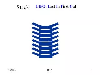
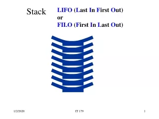
STACK and Stack Pointer. Stack Definition and Characteristics. Stack is a specialized memory segment which works in LIFO (Last In-First Out) mode. Managed by the Stack Pointer Register (SP) Hardwired stack: physically defined, cannot change

E N D
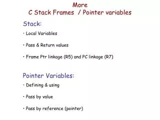
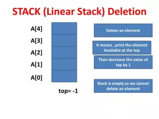
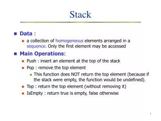
Stack Definition and Characteristics • Stack is a specialized memory segment which works in LIFO (Last In-First Out) mode. Managed by the Stack Pointer Register (SP) • Hardwired stack: physically defined, cannot change • Software defined: First address in stack defined by initialization of SP (by user or by compiler) • Stack Operations: • PUSH: storing a new data at the next available location • POP or PULL: retrieving last data available from the sequence (to be stored in some destination) • Important Note: A retrieved data is not deleted, but cannot be retrieved again with a stack operation • Top of Stack (TOS): memory address used in the stack operation (different for push or pop)
Basics of stack operation Empty at start (Only garbagge) X x x x x x x x x x Push TOS
Basics of stack operation PUSH (garbage not shown) D0 Push TOS Pop TOS
Basics of stack operation PUSH D0 D1 Push TOS Pop TOS
Basics of stack operation PUSH D0 D1 D2 Push TOS Pop TOS
Basics of stack operation POP D0 D1 D2 Push TOS Pop TOS
Basics of stack operation PUSH D0 D1 D3 Push TOS Pop TOS
Basics of stack operation POP D0 D1 D3 Push TOS Pop TOS
Basics of stack operation POP D0 D1 D3 Push TOS Pop TOS
Software Defined Stack Grows Downwards xxxx xxxx D0 PopTOS xxxx D0 Push TOS PopTOS D1 Push TOS xxxx-N xxxx-N xxxx-N Push TOS xxxx-2N xxxx-2N xxxx-2N xxxx-3N xxxx-3N xxxx-3N xxxx-4N xxxx-4N xxxx-4N Empty After a push After a push xxxx D0 xxxx D0 xxxx D0 D1 xxxx-N D1 PopTOS D1 xxxx-N xxxx-N D2 xxxx-2N PopTOS PopTOS D2 D3 xxxx-2N xxxx-2N Push TOS xxxx-3N Push TOS Push TOS xxxx-3N xxxx-3N xxxx-4N xxxx-4N xxxx-4N After a pop After a push After a push
Stack and Stack Pointer • The Stack Pointer contents is an address associated to the stack operation • The contents of SP is sometimes called Top-of-Stack • Since contents is unique, and two addresses are associated to the TOS, there are 2 possibilities: • SP contains the PUSH-TOS (Example: Freescale) • SP contains the POP TOS (Example: MSP430)
SP points to PUSH TOS • To do a PUSH: • 1. Store (SP) Data • 2. Update SP SP - N • To do a POP: • 1. Update SPSP+N • 2. Retrieve Dest(SP) • These steps are done automatically by CPU. D0 D1 PopTOS D2 (SP+N) Push TOS (SP)
SP points to POP TOS • To do a PUSH: • 1. Update SP SP -N • 2. Store (SP) Data • To do a POP: • 1. Retrieve Dest(SP) • 2. Update SPSP+N • These steps are done automatically by CPU. D0 D1 PopTOS (SP) D2 Push TOS (SP-N)
Stack Pointer in MSP430 • SP is register R1 • It is always even, since the least significant bit is hardwired to 0 • There is an error if user tries to load an odd number onto SP • It points to the ‘last pushed item’ (first to pop) • N=2: That is, update is always +- 2. • If pushing a byte, the msb of the word becomes garbage
Important Remarks • Without any reference to the actual meaning of SP contents, and the fact that the address for pushing and pulling are different, the following conventions are generally adopted: • Contents of SP is called TOP-OF-STACK (TOS) • PUSH operation is denoted as (TOS) source • POP or PULL operation is denoted as dest (TOS) • You should be aware of differences!!
INSTRUCTION SET (PART 1) General Introduction
General Introduction (1) • Instruction operate with data or “addresses”. • Two items are needed to define an instruction: • OpCode: What is the operation • Addressing mode: Where is data • Additional instruction operations may include size of operands or other modifiers.
General Introduction (2) • The maximum number of operands depend on system design • Most small microcontrollers work with two operands. Three is rare • The number and type of instructions depend on the MCU model • Most contain a common set or type
Operations types (1) • Data transfer (also called load or store): • Copy in destination a source dest source • Most transfers do not erase source. • Arithmetic and Logic Operations: • Of the type dest dest * operand2, • Special case is when two destinations are needed • Logic operations may be bitwise
Instruction Types • Register operations: Shift, roll and rotation • Flow program operations: On execution, they modify the content of the PC register • Jump instructions PC New Address • Subroutine instructions: Call and Return • Interrupt instructions: Return from Interrupt.
Data Transfer Instructions • Move: dest source • Push: (TOS) source • Pop or Pull: dest (TOS) • Input: dest (Input Port) • Output: (Output port) Source • Swap: dest <- - > source (exchange of contents; both operands are erase and reloaded)
Arithmetic instructions (1)Addition and Subtraction • Addition: dest dest + src • Addition with carry: dest dest + src + Carry Flag • Subtraction: Usually with two’s complement addition • Subtraction itself: dest dest – src • Subtraction with borrow : dest dest – src – BF or dest dest + NOT(src) + CF • Compare operation: dest – src; only flags affected
Arithmetic instructions (2)Multiplication and division • Not all microcontrollers’ ALU’s implement these operations. • Operands and destination sizes are of outmost importance. • Multiplication: dest dest x src • or dest1-dest dest x src • Division: dest1- dest2 dest/src • dest1 and dest2 are for quotient and residue
Logic Instructions (1) • Bitwise and not bitwise • Most microcontrollers support only bitwise • Non bitwise logic operation principles: • Yield a boolean result (usually in a flag) • In source, “1” means operand is not zero; “0” means operand is zero • Used mainly in high performance systems or as part of “high level” instructions
Bitwise Logic Operations (1) • dest dest*source means dest(j)dest(j)*source(j) • Bitwise operations permit individual bit manipulations • The source is usually called “mask” • “1”s in mask indicate which bits are to be affected • AND: dest dest .AND. src • OR: dest dest .OR. src • XOR: dest dest .XOR. Src • NOT: dest NOT(dest)
Bit manipulation : CLEAR 0.AND.X=0; 1.AND.X=X To clear specific bits in destination, the binary expression of the source has 0 at the bit positions to clear and 1 elsewhere
Bit manipulation : SET To set specific bits in destination, the binary expression of the source has 1 at the bit positions to set and 0 elsewhere 0.OR.X=X; 1.OR.X=1
Bit manipulation : TOGGLE To toggle specific bits in destination, the binary expression of the source has 1 at the bit positions to invert and 0 elsewhere 0.XOR.X=X; 1.XOR.X=X’
Shifts, rolls and rotates • Shift (or roll) right logically: • 0 dest(N-1)dest(N-2) …. dest(1) dest(0) CF • Shift left: • C dest(N-1) dest(N-2) …. dest(1) dest(0) 0 • Shift (or roll) right arithmetically: • Dest(N-1) dest(N-1)dest(N-2) …. dest(1) dest(0) CF • Rotate right through: • CFolddest(N-1)dest(N-2) …. dest(1) dest(0) CF
Program Flow Instructions (1)Jumps or Branch -- • ACTION: PC NewAddress • Unconditional jumps: (jmp) • GOTO!!!!!!!!!!! Ohhhhhhh!!!!!! • Conditional jumps: test a flag condition • Basic tools for decisions
Example 2: Repeat process N times Counter N Label: Do process counter counter -1 Jump if not zero to Label
INSTRUCTION SET (Part 2) 1. Machine instructions
Machine Instruction • System “understands” only 0’s and 1’s. • A set of Word(s) processed in the instruction register becomes an instruction • The instruction may consists of one or several words • The first word is the INSTRUCTION WORD • The size of instruction words may be different or not, depending on CPU, IR, and if Harvard or Von Neumman architecture.
Instruction Word Structure • OpCode: (Operating Code)Field of bits in the instruction word that indicates what operation is done • Operands and Addressing Modes Fields: Field(s) of bits indicating which operands are used in the transaction and where to find data. • Operands may be implicitly included (implicit operand) • The complete structure is CPU dependent.
EXAMPLE: MSP430 INSTRUCTIONS (1/4 )1. General facts • Instructions are divided in four groups • Two-operand instructions (source and destination) • One-operand instructions (source OR destination) • Jump instructions (Operand is an offset) :implicit operand PC • Return from Interrupt (RETI) instruction: Implicit operands PC and SR: 1300h • Note: TI user guides classify RETI as a one operand instruction
EXAMPLE: MSP430 INSTRUCTIONS (2/4 )2. Two Operand Instructions • Bits 15-12: OP-CODE (4 to F) • Bits 11-8: Source info • Bits 7-4: Operands and addressing modes • Bits 3-0: Destination info
EXAMPLE: MSP430 INSTRUCTIONS (3/4 )3. Single Operand Instructions • Bits 15-7: OP-CODE (Most significant nibble is 1) • Bit 6: (W/B) 0 for word size operand, 1 for byte size • Bits 5-4: Addressing mode for operad • Bits 3-0: Operand info
EXAMPLE: MSP430 INSTRUCTIONS (4/ 4)4. Jump Instructions • Bits 15-13: OP-CODE • Bit 12-10: Condition statement (8 conditions) • Bits 9-0: 10-bit signed offset for PC (-512 to 511) • Notes: • Most significant nibble is 2 or 3 • To effectuate jump, PC PC + 2 (Offset) • Maximum jump size 1K: -1,024 to +1,022
Instruction Set 2. Assembly language
Assembly Language Characteristics • Instructions in assembly language are “human friendly” notations for machine instructions • Each assembly language instruction corresponds to one machine instruction only, and viceversa • Components of instruction: • Mnemonics: associated to OpCode (and other information in instruction) • Operands: Written in a special syntax form called Addressing Mode • IMPORTANT: Assembly is proper to microcontroller family.
Mnemonics examples for MSP430 (1a/3) Dual Operand Instructions Notes: 1. **** .w means that bit 6 (B/W) is 0. (Word size operands) 2. ****.b means that bit 6 (B/W) is 1. (Byte size operands) 3. Suffix w may be omitted (mov.w = mov)
Mnemonics examples for MSP430 (2/3) Single Operand Instructions and RETI Instruction reti has no explicit operands, and only a 16-bit opcode: 1300