Download
1 / 40

E N D
Chapter-4 (Capacitance) Capacitor:Two conductors of arbitrary shape completely isolated from each other and their surroundings form a capacitor. No matter what their shape, these conductors are called plates. When the capacitor is charged by connecting the plates to the opposite terminals of a battery, equal and opposite charges (say +q and –q) appear on the two plates of the capacitor. By charge of a capacitor we mean the absolute value of the charge on either plate, the net charge on the capacitor being zero. The potential difference between the plates of the capacitor is the potential difference of the battery. The mechanical process of storing charges in a conductor is called capacitor. A capacitor is formed by two conductors separated by a small distance.
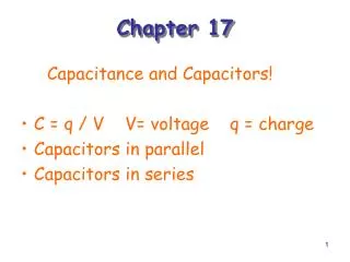
Chapter-4 (Capacitance) Capacitance: The charge q of a capacitor is found to be directly proportional to the potential difference between the plates. Or, q ∞ V or, q = CV or, C = q/V. The proportionality constant C is called capacitance of the capacitor. Its value depends on The geometry of each plate The distance between the plates The medium in which the plates are immersed. The amount of charge needed to increase the potential of a body by 1 unit is called its electric capacitance. It is a scalar quantity and its S. I. unit is Coulomb per volt called Farad.
Chapter-4 (Capacitance) Calculation of capacitance Capacitance of a parallel plate capacitor: A parallel plate capacitor formed of two parallel conducting plates of area A and separated by a distance d as shown in Fig-1. If the plates are connected to the opposite terminals of a battery, then a charge +q appear on one plate and a charge –q on the other. If d is small enough compared to the plate dimensions, the electric field strength E between the plates will be uniform.
Chapter-4 (Capacitance) Fig-1: Parallel plate capacitor
Chapter-4 (Capacitance) Let us imagine a Gaussian surface of height h closed by plane caps of area A of the same shape and size of the capacitor plates. The flux of E is zero for the part of the Gaussian surface that lies inside the top capacitor plate because the electric field inside a capacitor carrying a static charge is zero. Thus, the only part of the Gaussian surface which contributes to the electric flux is the Gaussian surface that lies between the plates. Here E is constant and according to Gauss’ law
Chapter-4 (Capacitance) The potential difference V between the plates can be given by, The capacitance of the parallel plate capacitor is given by, From eqn. (3), it is seen that the capacitance depend only on geometrical factors, namely, the plate area A and the plate separation d.
Chapter-4 (Capacitance) Example-1: A plane parallel plate capacitor has circular plates of radius 10.0 cm, separated by a distance of 1.00 mm. How much charge is stored on each plate when their electric potential difference has the value 100 V? Self Assesment-1: The area of each plate of an air filled parallel plate capacitor is 1.1 × m2. What must be the separation between the plates, if the capacitance is to be 1.0 F? [Ans: 0.9735 mm]
Chapter-4 (Capacitance)
Chapter-4 (Capacitance)
Chapter-4 (Capacitance)
Chapter-4 (Capacitance)
Chapter-4 (Capacitance)
Chapter-4 (Capacitance)
Chapter-4 (Capacitance)
Chapter-4 (Capacitance) Capacitance of a cylindrical capacitor: Fig-2 also serves to show a cross section of a cylindrical capacitor of length l formed by two co-axial cylinders of radii a and b. The length of the capacitor is assumed to be much greater than its radius, i.e., l>>b. Each plate contains a charge of magnitude q. As a Gaussian surface let us construct a coaxial cylinder of radius r and length l closed by end caps. Applying Gauss’s law we obtain,
Chapter-4 (Capacitance)
Chapter-4 (Capacitance)
Chapter-4 (Capacitance) Example-4: The space between the conductors of a long coaxial cable, used to transmit TV signals, has an inner radius a = 0.15 mm and an outer radius b = 2.1 mm. What is the capacitance per unit length of this cable? Solution:
Chapter-4 (Capacitance) Self Assesment-4: The space between the conductors of a long (10 cm) coaxial cable, used to transmit radio signals, has an inner radius of 0.18 mm and an outer radius of 2.00 mm. What is the capacitance of this cable? If the potential difference between the radii is 100 V, calculate the amount of charge that the capacitor can store. [Ans: 5.28 × 10⁻¹¹ F, 5.28 × 10⁻⁹ C]
Chapter-4 (Capacitance) Capacitors in Series and in Parallel Capacitors are one of the standard components in electronic circuits. Moreover, complicated combinations of capacitors often occur in practical circuits. It is, therefore, useful to have a set of rules for finding the equivalent capacitance of some general arrangement of capacitors. It turns out that we can always find the equivalent capacitance by repeated application of two simple rules. These rules related to capacitors connected in series and in parallel.
Chapter-4 (Capacitance) Fig-4: Two capacitors connected in parallel.
Chapter-4 (Capacitance) We consider two capacitors connected in parallel: i.e., with the positively charged plates connected to a common ``input'' wire, and the negatively charged plates attached to a common ``output'' wire as shows in Fig-4 In this case, the potential difference across the two capacitors is the same, and is equal to the potential difference between the input and output wires. The total charge Q , however, stored in the two capacitors is divided between the capacitors, since it must distribute itself such that the voltage across the two is the same. Since the capacitors may have different capacitances, C1 and C2, the charges Q1 and Q2 may also be different. The equivalent capacitance, Ceq of the pair of capacitors is simply the ratio Q/V, where Q = Q1 + Q2 is the total stored charge.
Chapter-4 (Capacitance)
Chapter-4 (Capacitance) We consider two capacitors connected in series: i.e., in a line such that the positive plate of one is attached to the negative plate of the other as shown in Fig-5. In fact, let us suppose that the positive plate of capacitor 1 is connected to the ``input'' wire, the negative plate of capacitor 1 is connected to the positive plate of capacitor 2, and the negative plate of capacitor 2 is connected to the ``output'' wire. In this case, it is important to realize that the charge Q stored in the two capacitors is the same. This is most easily seen by considering the ``internal'' plates: i.e., the negative plate of capacitor 1, and the positive plate of capacitor 2. These plates are physically disconnected from the rest of the circuit, so the total charge on them must remain constant.
Chapter-4 (Capacitance) Assuming, as seems reasonable, that these plates carry zero charge when zero potential difference is applied across the two capacitors, it follows that in the presence of a non-zero potential difference the charge +Q on the positive plate of capacitor 2 must be balanced by an equal and opposite charge –Q on the negative plate of capacitor 1. Since the negative plate of capacitor 1 carries a charge, -Q the positive plate must carry a charge +Q. Likewise, since the positive plate of capacitor 2 carries a charge, +Q the negative plate must carry a charge -Q. The net result is that both capacitors possess the same stored charge Q.
Chapter-4 (Capacitance) The potential drops, V1 and V2, across the two capacitors are, in general, different. However, the sum of these drops equals the total potential drop V applied across the input and output wires: i.e., V = V1 + V2,. The equivalent capacitance of the pair of capacitors is again Ceq = Q/V. Thus, Fig- 5: Two capacitors connected in series.
Chapter-4 (Capacitance)
Chapter-4 (Capacitance) Example-5: Find the equivalent capacitance of the combination as illustrated in the following figure. Assume C1 = 10 μF, C2 = 5 μF, C3 = 4 μF and V = 100 volts.
Chapter-4 (Capacitance)
Chapter-4 (Capacitance)
Chapter-4 (Capacitance)
Chapter-4 (Capacitance)
Chapter-4 (Capacitance)
Chapter-4 (Capacitance)
Chapter-4 (Capacitance)
Chapter-4 (Capacitance) Self Assesment-8: An isolated conducting sphere whose radius is 10 cm carries a charge of 1.5 nC. (i) How much energy is stored in the electric field of this charged conductor? (ii) What is the energy density at the surface of the sphere? [Ans: 1.01 × 10⁻⁷ J , 8.04 × 10⁻⁶ J/m3.] Self Assesment-9: A plane –parallel plate capacitor has circular plates of radius 15.0 cm, separated by a distance 2.00 mm. (i) How much charge is stored on each plate when their electric potential difference is 500 V? (ii) Calculate the electric field, the electric field energy density and the energy stored in the capacitor. [Ans:1.56× 10⁻⁷ C, 250000 V/m, 0.277 J/m3, 3.91 × 10⁻⁵ J. ]
Chapter-4 (Capacitance) Capacitance with dielectric: Dielectric is an insulating material such as mineral oil, glass or plastic, etc. The effect of the presence of a dielectric in the space between the plates of a capacitor was first investigated by Michael Faraday. Faraday constructed two identical capacitors, filling one with dielectric and the other with air under normal conditions. Faraday’s experiment showed when both the capacitor were charged to the same potential difference, the charge on the capacitor with dielectric was greater than that on the other. Since q is larger for the same V with the dielectric present, it follows from relation C = q/V that the capacitance of a capacitor increases if a dielectric is placed between the plates. If C is the capacitance of the
Chapter-4 (Capacitance)
Chapter-4 (Capacitance)