Download
1 / 16
160 likes | 302 Vues
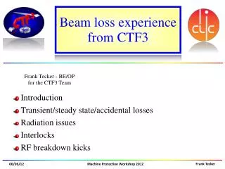
Some Results and Analysis from CTF3. The CTF3 Facility. Drive beam. Delay loop. X4. Combiner ring. 12 GHz Stand-alone Test Stand. 12 GHz Stand alone Test-stand. Test beam Line. Two-beam Test Stand. CALIFES Probe beam. Test Beam Line. Jan Kovermann Friday 10.30. 140 m.

E N D
Some Results and Analysis from CTF3 Some Results and Analysis from CTF3 W. Farabolini - A. Palaia
The CTF3 Facility Drive beam Delay loop X4 Combiner ring 12 GHz Stand-alone Test Stand 12 GHz Stand alone Test-stand Test beam Line Two-beam Test Stand CALIFES Probe beam Test Beam Line Jan Kovermann Friday 10.30 140 m Steffen Doebert Wednesday 13.15 • An unique place where a beam is really accelerated at high gradient • Great flexibility of RF production (power and pulse length) • Highly instrumented Test Stand and beam lines • Low repetition rate (5 Hz max. – presently 0.8 Hz) • Complex to operate Some Results and Analysis from CTF3 W. Farabolini - A. Palaia
The Two Beam Test Stand Drive beam Probe beam • Two lines hosting vacuum tanks for PETS and for ACS • A complete set of diagnostics for beams, RF phase / power measurements and breakdown detection • Quite a versatile RF layout Some Results and Analysis from CTF3 W. Farabolini - A. Palaia
Contents • Statistical analysis • BDR – overview of recorded experiments • BD’s time distribution and Poisson law • RF exposure time before BD and time power law • Signal processing analysis • RF signals without BDs • RF input reaction to BDs • BDs locations • Kick measurements during BDs • New diagnostics and possible improvements Some Results and Analysis from CTF3 W. Farabolini - A. Palaia
BDR from the last experiments R. Corsini – CLIC Project Meeting, 9 Dec. 2011 • Only few records are meaningful for statistics Some Results and Analysis from CTF3 W. Farabolini - A. Palaia
Numbers of RF pulses before a BD How far BDs occur randomly and independently of one another? Histograms and zoom on bins below 20 pulses before BD showing the cluster effect. [Number of BD] [Number of RF pulses from previous BD] Some Results and Analysis from CTF3 W. Farabolini - A. Palaia
BDs time distribution and Poisson law • Randomly distributed events should follow the Poisson law. k : number of BDs, l : BDR x number of pulses • Clusters make the BD probability (BDR) non stationary 2011-12-06 2011-12-03 Low BDR High BDR [Pulse number] [Pulse number] Some Results and Analysis from CTF3 W. Farabolini - A. Palaia
Discarding the cluster events 2011-12-06 [Pulse number] [Rejected cluster size] Evolution of mean/s with the cluster size rejection (1 for a Poisson distribution) Rejecting clustered BDs leads the BDs events to be more “Poisson Like” Some Results and Analysis from CTF3 W. Farabolini - A. Palaia
Probability of one single BD within a given number of RF pulses • Poisson law for k = 1 and l computed using the raw BDR (not a fitted one) • No clusters rejection needed at low BDR (BDR =0.0003) Clusters rejected up to 20 pulses between BDs (BDR = 0.003) [Pulse number] [Pulse number] Some Results and Analysis from CTF3 W. Farabolini - A. Palaia
RF exposure time before BD • Exposure time = RF transmitted pulse length • Dependent on edges definition (especially with recirculation pulse shape) Exposure time before BD [ns] Histogram of exposure time before BD Some Results and Analysis from CTF3 W. Farabolini - A. Palaia
BDR as function of exposure time • Hypothesis : BDs occurred before a given time have the same statistic as if the pulse length would have been this exact time. • It will be very interesting to draw the same plot with various pulse lengths (looking for a possible “fatigue” effect) Max RF pulse length [BDR] Exposure time before BD [ns] Some Results and Analysis from CTF3 W. Farabolini - A. Palaia
RF signals without BDs • Without BD all signals are quite stable: good RF power production by the Drive Beam [MW] 100 superposed signals [ns] Average input signal and steps detection showing the recirculation loop delay of 31 ns Quite stable pulse length and power characteristics Some Results and Analysis from CTF3 W. Farabolini - A. Palaia
Evidence of ACS BDs effect on input power • The reflected power is likely to change randomly the phase of the PETS recirculation loop and consequently to modify the produced power 25 ns 19 ns A BD in the ACS affects the PETS output Bouncing of an early BD reflected power Some Results and Analysis from CTF3 W. Farabolini - A. Palaia
BD location determination Reflected rising edge Transmitted falling edge 1st method (transmission): looking at BD position when BD strikes Input falling edge BDs in cell # Reflected falling edge Cells 5-6 are the most affected by BDs Reflected /Input power ratio 2nd method (echo): looking at BD position when RF pulse stops D time Reflected - Input • Using the Reflected power signal is likely to introduce a bias in the BD cell position detection • Attend to use PM and FCU signals instead (not fully successful up to now) Some Results and Analysis from CTF3 W. Farabolini - A. Palaia
Kick Measurement 29 AUG 2011 data preliminary result (to be confirmed); • Analysis on ~170 BD events, 2-Gaussian fit on the screen • kicks corresponding to a transverse momentum between 10 and 40 keV/c (measurements at NLCTA within 30 keV/c, cfr. Dolgashev, SLAC-PUB-10668) Some Results and Analysis from CTF3 W. Farabolini - A. Palaia
The next run… • Collect more data about beam kicks • Use the RF phase information • Collect more BDs data at reasonable BDR • Long shift at stable power characteristics • Higher repetition rate • Additional diagnostics used • PM looking inside the TD24 through FCU mirror • New re-entrant cavity BPMs • Flash Box, • Wakefield monitor • Apply new ideas exchanged during HG 2012 in KEK Some Results and Analysis from CTF3 W. Farabolini - A. Palaia