Download
1 / 20
220 likes | 357 Vues
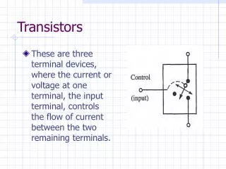
Transistors. Review : What is a Transistor ?. Collector. NPN Transistor Rules: V C > V E V B = V E + 0.6 Volts I C = I B . I C : Collector Current. Base. I B : Base Current. I E : Emitter Current. I E = I C + I B I E = (1 + ) I B.

E N D
Transistors Tim Sumner, Imperial College, Rm: 1009, x47552
Review : What is a Transistor ? Collector NPN Transistor Rules: VC > VE VB = VE + 0.6 Volts I C = I B IC : Collector Current Base IB : Base Current IE : Emitter Current I E = I C + I B I E = (1 + )I B Emitter FOR MORE INFO... Relevant Books: Art of Electronics + Lab: Harowitz and Hill Electronic Circuits: E.C. Lowenberg, SCHAUM SERIES Electric Circuits: J.A. EDMINISTER SCHAUM SERIES Tim Sumner, Imperial College, Rm: 1009, x47552
Some Transistor Applications I + V • Follower: • Current Source + V Load IC Vin IC Vin= 5.6 V Vout= Vin+ 0.6 Volts Vout= 5.0 V IE R = 5 K IE = 1 mA - V Tim Sumner, Imperial College, Rm: 1009, x47552
Some Transistor Applications II • Push-Pull : • Common Emitter Amplifier : + V + V RC >> Vout >> Qup Vout Vin = VB Vin = VE RE << IE = IC >> Qdown - V Tim Sumner, Imperial College, Rm: 1009, x47552
The Emitter Follower I Given : Vcc = 15 Volts Ic = 0.5 mA; = 100 f(100 Hz) = 3 db What about C1 ? Vcc Source R1 Ic Load C1 1F 10 K ~ 4.7 K R2 R3 Rbase= VB/IB = 1.64 M (2) RTH(divider) = 1/10 RB RB = 164 K R1 = R2= 328 K (1) R3=7.5 V/0.5 mA = 15K Tim Sumner, Imperial College, Rm: 1009, x47552
The Emitter Follower II (3) Think of an RC filter (high-pass) . 15K is parallel to 4.7 K and the whole think times 358 K ; parallel with 328 K 112 K; So f=(1/2RC) 0.014 F Vcc Source 328 K Ic Load C1 1F 10 K ~ 4.7 K 328K 15 K = 100 f(100 Hz) = 3 db Tim Sumner, Imperial College, Rm: 1009, x47552
Emitter Follower (a bit diff.) Rin=Rload(1+) Rout=Rsource/(1+) Tim Sumner, Imperial College, Rm: 1009, x47552
Common Emitter Amplifier Gain = R5/R2 Rout=R5 Tim Sumner, Imperial College, Rm: 1009, x47552
Common Emitter Amplifier II Tim Sumner, Imperial College, Rm: 1009, x47552
The Ebers-Moll Model for BJT Tim Sumner, Imperial College, Rm: 1009, x47552
Temperature Effects Tim Sumner, Imperial College, Rm: 1009, x47552
Temperature Effects and Current Mirrors Tim Sumner, Imperial College, Rm: 1009, x47552
Exercises • Make a Current Source using a transistor • Make common emitter follower • Make a Common Emitter Amplifier Tim Sumner, Imperial College, Rm: 1009, x47552
Making Gates using Transistors I +5 Volts InPut A A .OR. B InPut B Tim Sumner, Imperial College, Rm: 1009, x47552
Making Gates using Transistors II InPut A A .OR. B InPut B Here is what we have made Tim Sumner, Imperial College, Rm: 1009, x47552
Exercise I Design and construct an AND gate using transistors and resistors : InPut A A .AND. B InPut B The AND gate TRUTH table Tim Sumner, Imperial College, Rm: 1009, x47552
Exercise I continued Verify the truth table ! You can set an input to ‘1’ by connecting it to +5 V by a resistor of 1K and you set it to ‘0’ by grounding it. 5 V ‘0’ InPut B ‘0’ A .AND. B InPut A ‘1’ 5 V Tim Sumner, Imperial College, Rm: 1009, x47552
Answer (almost): TTL CMOS Not quite because this is a NAND gate but we do know by now how to invert using a transistor Tim Sumner, Imperial College, Rm: 1009, x47552
Important conclusion You may understand by now that the inputs have no ability to set signals high or low. In contrast to this the outputs can drive signals to High or Low Tim Sumner, Imperial College, Rm: 1009, x47552
Remember: Inputs draw no current. 1K resistors to +5 V can set inputs to high or they can be set low by connecting to ground. Outputs can draw current and can force lines to low or high. Tim Sumner, Imperial College, Rm: 1009, x47552