Download
1 / 39
390 likes | 677 Vues
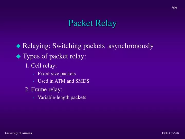
Packet Relay. Relaying: Switching packets asynchronously Types of packet relay: 1. Cell relay: Fixed-size packets Used in ATM and SMDS 2. Frame relay: Variable-length packets. Advantages of Fixed-Size Packets. Simple switch-hardware design Hardware store-and-forward is easier

E N D
Packet Relay • Relaying: Switching packets asynchronously • Types of packet relay: 1. Cell relay: • Fixed-size packets • Used in ATM and SMDS 2. Frame relay: • Variable-length packets ECE 478/578
Advantages of Fixed-Size Packets • Simple switch-hardware design • Hardware store-and-forward is easier • Dynamic storage allocation is easier (no memory fragmentation) • More deterministic scheduling (for performance guarantees) • High degree of parallelism in large switches • Synchronized multiprocessors • Multiple levels of buffering can be easily clocked ECE 478/578
Disadvantages of Fixed-Size Packets • Segmentation and reassembly (SAR) • Overhead in the case of small-size cells ECE 478/578
Integrated Services Digital Network (ISDN) • Evolutionary technology from digital telephony • Intended as a digital interface for voice and data • More popular in Europe • ISDN terminology: • Functional grouping: A set of capabilities in an ISDN user interface (similar to layer functions) • Reference points: Logical interfaces between functional groupings (similar to SAPs) ECE 478/578
ISDN Specification • Types of functional groupings: • Terminal Type 1 and 2 (TE1 and TE2) • Network Termination 1 and 2 (NT1 and NT2) • Four reference points: R, S, T, and U ECE 478/578
T U S TE 1 NT 2 NT 1 LT/ET Network T U R S TE 2 TA NT 2 NT 1 LT/ET Typical ISDN Topology ECE 478/578
Typical ISDN Topology (Cont.) • TE1 = end-user ISDN terminal • TE2 = non-ISDN terminal • TA = terminal adaptor • NT1 = device that connects 4-wire subscriber wiring to 2-wire local loop. Responsible for physical layer functions • NT2 = more complex than NT1. Contains layer 2 and 3 functions. Performs concentration ECE 478/578
ISDN Access Rates • Basic Rate Interface (BRI) • Two 64-kbps B channels for data • One 16-kbps D channel for control (out of band) • Designated as 2B+D • Up to eight TE1s can be multiplexed onto a BRI • Primary Rate Interface (PRI) • 23 64-kbps B channels for data (total of 1.544 Mbps) • One 64-kbps D channel for control • Designated as 23B+D • In Europe the PRI consists of 31B+D (E1 line) ECE 478/578
Broadband ISDN (B-ISDN) • Set of protocols that is standardized by ITU-T • Started as an extension of ISDN. However, ISDN and ISDN interfaces are NOT compatible • ATM is the transport protocol for B-ISDN ECE 478/578
Driving Forces Behind B-ISDN • Emergence of bandwidth-intensive applications • Desire to integrate data, voice, and video over a single channel (why?) • Need to provide performance guarantees for real-time applications ECE 478/578
frame frame frame frame Synchronous Transfer Mode (STM) • Based on time-division multiplexing (TDM) • Each connection is reserved a time slot • Bandwidth is wasted if user is idle Stream #1 Time Division Multiplexer Stream #1 Stream #1 wasted bandwidth ECE 478/578
1 1 1 1 Stream #1 Statistical Multiplexer 2 2 1 2 3 1 1 2 1 3 Stream #1 3 3 Stream #1 Asynchronous Transfer Mode (ATM) • Based on statistical (i.e., asynchronous) multiplexing • Bandwidth is allocated on demand • Each packet (cell) carries its connection ID ECE 478/578
So What is ATM? • Transport technology for B-ISDN • Based on fixed-length packets (cells) • A cell consists of 53 bytes: • User payload: 48 bytes • Cell header: 5 bytes • Hardwired store-and-forward architecture • Connection-oriented fast packet switching! ECE 478/578
What Does ATM Provide? • Efficient bandwidth utilization (via statistical multiplexing) • Quality of service (QoS) • Maximum cell transfer delay • Cell delay variation (jitter) • Cell loss rate • Cell sequencing (important for real-time apps) • Unified transport solution for diverse traffic types • Scalability ECE 478/578
Cell Size Considerations • Transmission efficiency • PL no. of payload bytes • HD no. of header bytes • Impact of cell loss on voice quality • Loss of 32-byte cell 4 ms interruption • > 32 ms interruption is quite disruptive • Echo cancellation ECE 478/578
B-ISDN Protocol Stack • Three “planes”: • User plane • Control plane • Management plane • Plane management • Layer management Plane Management Layer Management User Plane Control Plane Higher Layers ATM Adaptation Layer ATM Layer Physical Layer ECE 478/578
B-ISDN Physical Layer • Consists of two sublayers: • Transmission Convergence (TC) sublayer • Physical Medium (PM) sublayer • Functions of the TC sublayer: • Generation/recovery of transmission frames • Transmission frame adaptation • Cell delineation • Cell header processing (HEC generation) • Cell rate decoupling ECE 478/578
B-ISDN Physical Layer (Cont.) • Functions of the PM sublayer: • Bit timing • Line encoding • Other medium-dependent functions ECE 478/578
Common Physical Layer Interfaces • Multimode Fiber: • 155 Mbps SONET STS-3c (SDH) • 100 Mbps 4B/5B coding • Single-Mode Fiber at 100 Mbps 4B/5B coding • Coax cable at 45 Mbps DS3 rate • Subrates (for ATM over unshielded twisted pair) • 51.84 Mbps • 25.92 Mbps • 12.96 Mbps ECE 478/578
SONET Hierarchy ECE 478/578
SONET STC-3c Physical Layer B-ISDN Specific Functions - HEC generation/verification - Cell scrambling/descrambling - Cell delineation - Path signal identification - Frequency justification/Pointer processing - Multiplexing - Scrambling/descrambling - Transmission frame generation/recovery Transmission Convergence Sublayer B-ISDN Independent Functions Physical Media Dependent Sublayer - Bit timing, Line coding - Physical medium ECE 478/578
1 2 3 1 1 2 2 3 5 5 5 3 ATM Layer Functions • Cell multiplexing and demultiplexing • VPI/VCI translation • Traffic management (e.g., shaping, policing) • Cell header processing (except for the HEC field) • Cell rate decoupling (for SONET and DS3) • OAM functions Switch 1 1 2 1 3 4 4 1 1 4 4 5 5 4 5 4 ECE 478/578
ATM Cell Format BIT 8 7 6 5 4 3 2 1 GFC 1 2 3 4 5 6 . . 53 VPI VCI VPI VCI OCTET VCI PT CLP HEC Cell Payload (48 octets) ECE 478/578
Remarks • The previous cell format is for the User-to-Network Interface (UNI) • Between an end-system and an ATM switch • An end system could be, an IP router with an ATM interface, a PC/workstation, or a LAN switch • In the Network-to-Network Interface (NNI), the GFC field is used as part of the VPI field • NNI is typically between two ATM switches • Two flavors of NNI are used (Private and Public) ECE 478/578
AAL ATM Physical ATM Switching User A User B AAL ATM ATM Network Physical UNI PNNI PNNI UNI = User Network Interface UNI = Private Network Node Interface PNNI ECE 478/578
VPI GFC VCI VPI VCI CLP VCI PT HEC Cell Payload (48 octets) Generic Flow Control (GFC) • Four bits in the cell header • Only in cells at UNI (intermediate switches overwrite it) • Intended for link-by-link flow control • Typically, GFC is not used ECE 478/578
Connection Identifiers • ATM uses a 2-level connection hierarchy: • Virtual channel connection (VCC or VC) • Virtual path connection (VPC or VP) • A VP is a bundle of VCs • Each connection has a VP identifier (VPI) and a VC identifier (VCI) • Cell switching is performed based on: • VPI alone (VP switching), or • Both VCI and VPI (VP/VC switching) VPI GFC VCI VPI VCI CLP VCI PT HEC Cell Payload (48 octets) ECE 478/578
Connection Identifiers (Cont.) • Some VPI and VCI values are reserved for signaling and control functions: • Connection requests: VPI=0, VCI=5 • PNNI topology state packets: VPI=0, VCI=18 • Resource Management (RM) cells: VCI=6 • VCI values < 32 are reserved for control functions • VCIs and VPIs have local scope ECE 478/578
VCI 1 VCI 2 VCI 1 VCI 1 VCI 2 VCI 2 VP and VP/VC Switching VPI 3 VPI 3 VCI 5 VCI 3 VPI 1 VPI 4 VPI 1 VP Switching VP/VC Switching ECE 478/578
Payload Type Meaning VPI GFC VCI VPI VCI CLP VCI PT HEC Cell Payload (48 octets) Payload Type (PT) Field 000 user cell, no congestion, cell type 0 001 user cell, no congestion, cell type 1 010 user cell, congestion indication, cell type 0 011 user cell, congestion indication, cell type 1 100 OAM cell (link-by-link) 101 OAM cell (end-to-end) 110 RM cell (used in ABR service) 111 reserved for future use ECE 478/578
VPI GFC VCI VPI VCI CLP VCI PT HEC Cell Payload (48 octets) Cell Loss Priority (CLP) • CLP = 1 for low priority • CLP = 0 for high priority • CLP is used in selective cell discarding to: • penalize greedy users (traffic policing) • request differential QoS (e.g., coded video) • CLP is a key parameter in traffic management ECE 478/578
VPI GFC VCI VPI VCI CLP VCI PT HEC Cell Payload (48 octets) Header Error Control (HEC) • Checksum over cell header • Performed by the physical layer • Corrects all single-bit errors • Detects about 84% of multiple-bit errors • Cells with multiple errors are discarded ECE 478/578
ATM Layer in the OSI Model • Different opinions: • Network layer (since it performs routing) • Data-link layer (in IP over ATM and in MPOA) • Physical layer (in LAN emulation) • Conclusion: • There is no 1-to-1 correspondence between B-ISDN and OSI layered models ECE 478/578
ATM Adaptation Layer (AAL) • Purpose: Adapt upper “applications” to ATM layer • Different applications have different needs Four AALs are used • AALs were originally classified according to: • Real-time versus non-real-time • Connection oriented versus connectionless • Constant bit rate (CBR) versus variable bit rate (VBR) ECE 478/578
AAL Functions • Segmentation and reassembly of upper-layer PDUs • Delay variation recovery • Cell losses recovery • Circuit emulation (e.g., voice over ATM) • Connectionless service over ATM • Clock synchronization • And others ... ECE 478/578
Convergence Sublayer (service specific part) Convergence Sublayer (common part) Segmentation & Reassembly Sublayer AAL Structure Note: In some AALs, the convergence sublayer consists of one part only ECE 478/578
Types of AAL 1. AAL1 • Intended for TDM-like circuit emulation • Supports clock synchronization and timing recovery • Provides sequence numbers 2. AAL2 • Optimized for the transport of VBR video traffic • Provides timing information and sequence numbers • Not quite popular ECE 478/578
Types of AAL (Cont.) 3. AAL3/4 • Provides both connectionless and connection-oriented services over ATM • Supports the multiplexing of messages from multiple users over the same VC • Not popular either 4. AAL5 • Intended for data applications (e.g., TCP over AAL5) • Provides minimal functionality • Most popular AAL ECE 478/578
Barriers to the Deployment of ATM • Lack of “killer applications” • Cost of new infrastructure • Other competitive technologies for LANs • Uncertainty about the new technology • Incomplete standards ATM is mainly being deployed in the Internet backbone and within specialized networks ECE 478/578