Download
1 / 25
250 likes | 263 Vues
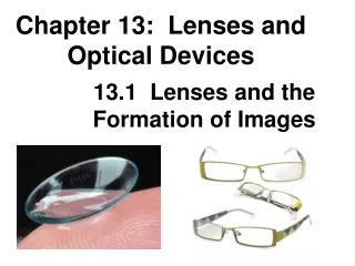
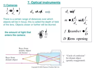
Chapter 33 Lenses and Optical Instruments. 33-2 The Thin Lens Equation; Magnification. Example 33-2: Image formed by converging lens. What are (a) the position, and (b) the size, of the image of a 7.6-cm-high leaf placed 1.00 m from a +50.0-mm-focal-length camera lens?.

E N D
33-2 The Thin Lens Equation; Magnification Example 33-2: Image formed by converging lens. What are (a) the position, and (b) the size, of the image of a 7.6-cm-high leaf placed 1.00 m from a +50.0-mm-focal-length camera lens?
33-2 The Thin Lens Equation; Magnification Example 33-3: Object close to converging lens. An object is placed 10 cm from a 15-cm-focal-length converging lens. Determine the image position and size (a) analytically, and (b) using a ray diagram.
Problem 14 14. (II) How far apart are an object and an image formed by an 85-cm-focal-length converging lens if the image is 2.95 larger than the object and is real?
33-3 Combinations of Lenses In lens combinations, the image formed by the first lens becomes the object for the second lens (this is where object distances may be negative). The total magnification is the product of the magnification of each lens.
33-3 Combinations of Lenses Example 33-5: A two-lens system. Two converging lenses, A and B, with focal lengths fA = 20.0 cm and fB = 25.0 cm, are placed 80.0 cm apart. An object is placed 60.0 cm in front of the first lens. Determine (a) the position, and (b) the magnification, of the final image formed by the combination of the two lenses.
33-4 Lensmaker’s Equation This useful equation relates the radii of curvature of the two lens surfaces, and the index of refraction, to the focal length:
33-4 Lensmaker’s Equation Example 33-7: Calculating f for a converging lens. A convex meniscus lens is made from glass with n = 1.50. The radius of curvature of the convex surface is 22.4 cm and that of the concave surface is 46.2 cm. (a) What is the focal length? (b) Where will the image be for an object 2.00 m away?
34 Waves versus Particles; Huygens’ Principle and Diffraction
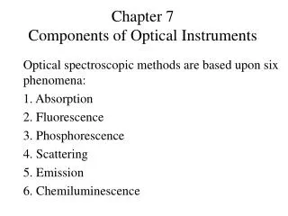
34-1 Waves versus Particles; Huygens’ Principle and Diffraction Huygens’ principle: every point on a wave front acts as a point source; the wave front as it develops is tangent to all the wavelets. wavefront wavelets
34-1 Waves versus Particles; Huygens’ Principle and Diffraction Huygens’ principle is consistent with diffraction: The wave bend in behind an obstacle, this is called diffraction
34-2 Huygens’ Principle and the Law of Refraction • Newton’s particle theory predicted that v2>v1 which is wrong when using geometry and speed of light speed changing in a medium. Refraction works only for v2<v1 • Foucault confirmed the Huygen’s wave theory in 1850 • Huygens’ principle can also explain the law of refraction (Snell’s Law). • As the wavelets propagate from each point, they propagate more slowly in the medium of higher index of refraction. • This leads to a bend in the wave front and therefore in the ray.
34-2 Huygens’ Principle and the Law of Refraction The frequency of the light does not change, but the wavelength does as it travels into a new medium: From the geometry in he figure
34-3 Interference – Young’s Double-Slit Experiment If light is a wave, interference effects will be seen, where one part of a wave front can interact with another part. One way to study this is to do a double-slit experiment:
34-3 Interference – Young’s Double-Slit Experiment Monochromatic wavelength (single wavelength) through two slits. If light is a wave, there should be an interference pattern.
Principle of Superposition When waves overlap, their amplitudes add Constructive Destructive l + + Phase Shifted 180°, , or /2 l = = Peaks line up with troughs Peaks line up with peaks
What are PHASE differences? Phase difference is a term used to describe the relative alignment of the peaks IN PHASE= two waves are lined up—constructive interference OUT of PHASE= one wave is upside down relative to the other—destructive interference
What causes Phase differences? Light travels different distances just like any other wave d1 Source 1 d2 Source 2 Constructive Interference when in phase Path difference is an integral number of wavelengths ∆d = d1-d2 = m Where m is an integer Destructive Interference when out of phase Path difference is a half integral number of wavelengths ∆d = d1-d2 = (m+1/2) Where m is an integer
34-3 Interference – Young’s Double-Slit Experiment The interference occurs because each point on the screen is not the same distance from both slits. Depending on the path length difference, the wave can interfere constructively (bright spot) or destructively (dark spot).
34-3 Interference – Young’s Double-Slit Experiment Between the maxima and the minima, the interference varies smoothly.
Young’s Double Slit Light from each slit travels to a screen where the waves interfere m = 0 m = -1 m = +1 m = +2 m = -2 m = fringe order l = distance to screen d = slit separation l Phase differences due entirely to path differences d
Young’s Double Slit Maxima : Constructive Interference - occur where Δd =s2-s1=dsinθ= m Y m = order = 0, 1, 2, … Minima: destructive Interference - occur where Δd = (m + ½) l Path difference d: distance between slits y:distance of the fringe from the axis center l: distance of the screen Small angles: tan θ= sin θ=θ d
Problem 8 8.(II) Light of wavelength 680 nm falls on two slits and produces an interference pattern in which the third-order bright fringe is 38 mm from the central fringe on a screen 2.6 m away. What is the separation of the two slits?