Download
1 / 20
290 likes | 541 Vues
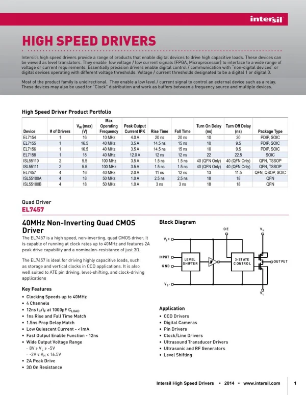
VCSEL High Speed Drivers. Bryan A. Weaver ECE-E641 February 27, 2003. light output. p-contact. active region. n-contact. oxide. What is a VCSEL?. Vertical Cavity Surface Emitting Laser. VCSEL Characteristics. Distributed-Bragg Reflector

E N D
VCSEL High Speed Drivers Bryan A. Weaver ECE-E641 February 27, 2003
light output p-contact active region n-contact oxide What is a VCSEL? Vertical Cavity Surface Emitting Laser
VCSEL Characteristics • Distributed-Bragg Reflector • Periodic Variation in Refractive Index in Direction of Wave Propagation • Short Cavity - Better Modal Purity • Feedback is Frequency Dependant
Applications of VCSELs Widely Used in Multi-Gigabit Optical Networks
How Do You Modulate A VCSEL? • Frequency Modulation • A VCSEL is a Resonant Oscillator • Frequency can’t be Easily Varied • Amplitude Modulation • Output is Directly Proportional to Drive Current
Optical Modulation Trade-Off • Optical Power • Jitter • Extinction Ratio • Undershoot • Speed • Reliability
Optical Modulation Trade-Off • Optical Power • Increased Modulation Current Results in Increased Optical Power and Increased Dissipation • Highest Level of Optical Power will Result in Best Signal to Noise Ratio at Receiver • Bit Error Rate (BER) Ultimate Measure of Optical System Performance
Optical Modulation Trade-Off • Jitter • Turn-On Delay • Data Dependant Difference in TON Between the Current Density of ITH and Absolute Zero • Carrier Density after one Zero will be Greater than after a few Consecutive Zeros • Reduced by Application of Bias Current IBIAS that is Greater than Threshold Current ITH • ITH is Determined by Difference Between Gain and Loss at the Lasing Wavelength.
Optical Modulation Trade-Off • Extinction Ratio • When Commanded Off a VCSEL is Still Biased Slightly-On • Difference in Optical Intensity Between On and Off Sacrifices Extinction Ratio (SNR) • Extinction Ratio is now Controllable only by Variations in Modulation Current IMOD
Optical Modulation Trade-Off • Undershoot • Relaxation Resonance • Leading Edge Pulse Ringing • Oscillatory Behavior Between Excess Carrier Generation and Recombination • Relaxation Resonance can be Reduced by Brief Period of Overdrive
Optical Modulation Trade-Off • Speed • Ultimate Speed is Limited by Relaxation Resonance • Thermal Drawbacks at MHz Rates and Below • Time Constant Modulated Characteristics
Optical Modulation Trade-Off • Reliability • Increased Optical Power Results in Decreased Reliability
VCSEL Drive Characteristics • Current Driven • All of the Previously Discussed Drive Parameters were Current and Temperature Dependant • What is Needed is a Temperature Compensated Current Source with Bandwidth that Extends into the Millimeter Wave Band
The Results Eye Diagram Tr = 60 pS, BW is Approximately 100 GHz
Can You Identify the Following? • Jitter • Relaxation Resonance • Delayed Carrier Recombination
Conclusions • Low BER Requires • High Optical Power • High Extinction Ratio • Low Undershoot • Low Jitter • High Speed (Bandwidth)