Download
1 / 40
630 likes | 1.24k Vues
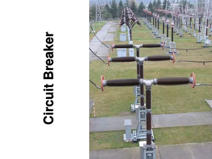
Circuit Breaker. STANDARDS. IEC 62271-100 High-voltage switchgear and controlgear – Alternating-current circuit-breakers. Definition.

E N D
STANDARDS • IEC 62271-100 High-voltage switchgear and controlgear – Alternating-current circuit-breakers
Definition “A mechanical switching device capable of making, carrying, and breaking currents under normal circuit conditions and also making, carrying, and breaking for a specified time, and breaking currents under specified abnormal conditions such as a short circuit.” [ IEEE Standard C.37.100-1992 ]
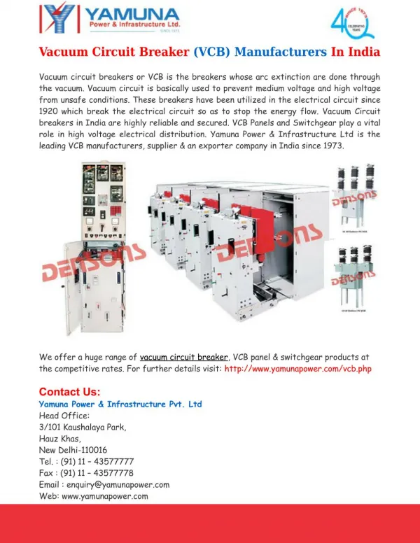
Type of Circuit Breakers • Air magnetic • Air blast • Oil • SF6 gas • Vacuum
Oil Circuit Breaker Three Tank Bulk Oil Circuit Breaker Minimum Oil Circuit Breaker
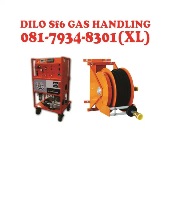
SF6 Circuit Breaker Dead Tank SF6 Circuit Breaker Live Tank SF6 Circuit Breaker
Circuit Breaker with Opening Resistors and Grading Capacitor
SF6 Puffer Type Breaker Operation Puffer (piston) method showing the 4 stages of the opening process, a) closed position, b) beginning of the opening movement, c) arcing contacts separate, d) open position, 1 fixed continuous current contact, 2 fixed arcing contact, 3 movable arcing contact, 4 movable continuous current contact, 5 compression cylinder, 6 compression piston, 7 actuating rod, 8 quenching nozzle
Puffer Principle Opening Open Closed
Technical Specification 1. Type designation for breaker 2. Class 3. Rated Voltage 4. Rated Frequency 5. Whether single pole or 3-pole operation 6. Rated Lightning Impulse Withstand Voltage a) To earth b) Across open circuit breaker 7. Rated Switching Impulse Withstand Voltage a) To earth b) Across open circuit breaker 8. Rated Power Frequency Withstand Voltage a) To earth b) Across open circuit breaker
Rated insulation levels for rated voltages of range I(1kV < Um ≤ 245 kV)[IEC 60071-1 Table 2]
Rated insulation levels for rated voltages of range II(Um > 245 kV)[IEC 60071-1 Table 3]
Rated insulation levels for rated voltages of range II[IEC 62271-1 Table2a]
Rated insulation levels for rated voltages of range II (Um > 800 kV) [IEC 62271-1 Amend.1 : 2011 Table2a]
Values of rated insulation levels for 1kV < Um ≤ 245 kV for highest voltages for equipment Um not standardized by IEC based on current practice in some countries[IEC 62271-1 Table B.1]
Technical Specification 9. Rated Current 10. Rated short time withstand current 11. Rated short circuit breaking current a) AC Component b) DC Component 12. Rated short circuit making current
Determination of short-circuit making and breaking currents, and of percentage d.c. component IMC : making current IAC : peak value of a.c. component [IEC 62271-100:2008 Fig.8] : percentage value of the d.c. component
Technical Specification 13. Rated out of phase breaking current 14. First pole to clear factor
First Pole to Clear Factor (kpp) • The first-pole-to clear factor is the ratio of the power frequency voltage across the first interrupting pole, before current interruption in the other poles, to the power frequency voltage occurring across the pole after interruption in all three poles.
First Pole to Clear Factor (kpp) • For systems with non-effectively grounded neutral, kpp is 1.5. • For three-phase to ground faults in systems with effectively earthed neutral, kpp is 1.3.
Technical Specification 15. Rated small inductive breaking current 16. Rated line charging breaking current 17. Rated cable charging breaking current
Preferred values of rated capacitive switching currents [Table9 IEC 62271-100:2008]
Technical Specification 18. Transient Recovery Voltage (TRV) a) terminal line faults b) short line faults
Transient Recovery Voltage (TRV) • The recovery voltage is the voltage which appears across the terminals of a pole of circuit breaker after current interruption.
Standard values of TRV forclass S1 circuit-breakers 1kV < Ur ≤ 72.5 kV [Table1 IEC 62271-100:2008]
Standard values of TRVfor class S2 circuit-breakers 15kV ≤ Ur ≤ 72.5 kV [Table2 IEC 62271-100:2008]
Standard values of TRV for effectively earthed systems100kV ≤ Ur ≤ 170 kV [Table3 IEC 62271-100:2008]
Standard values of TRV for non-effectively earthed systems100kV ≤ Ur ≤ 170 kV [Table4 IEC 62271-100:2008]
Standard values of TRV for effectively earthed systemsUr ≥ 245 kV [Table5 IEC 62271-100:2008]
Technical Specification 19. Rated operating sequence 20. Rated a) Break time b) Opening time c) Closing time 21. Number of breaking operation before inspection and maintenance of contact: a) At 100% rated current b) At 50% Short circuit current c) At 100% Short circuit current
Max. permissible number of interruptions as a functionof the breaking current for 400kV Alstom CB.
Max. permissible number of interruptions as a functionof the breaking current for 400kV Siemens CB.
Technical Specification 22. Min. creepage distance 23. For SF6 circuit breaker: a) Nominal service gas pressure b) Gas refill alarm pressure c) Blocking gas pressure d) Total volume of the gas 24. Operating mechanism: a) Type of mechanism b) Motor Type c) Motor and control voltage d) Heater voltage e) Time required by motor to charge the spring completely f) Degree of protection of operating mechanism