Download
1 / 76
770 likes | 1.01k Vues
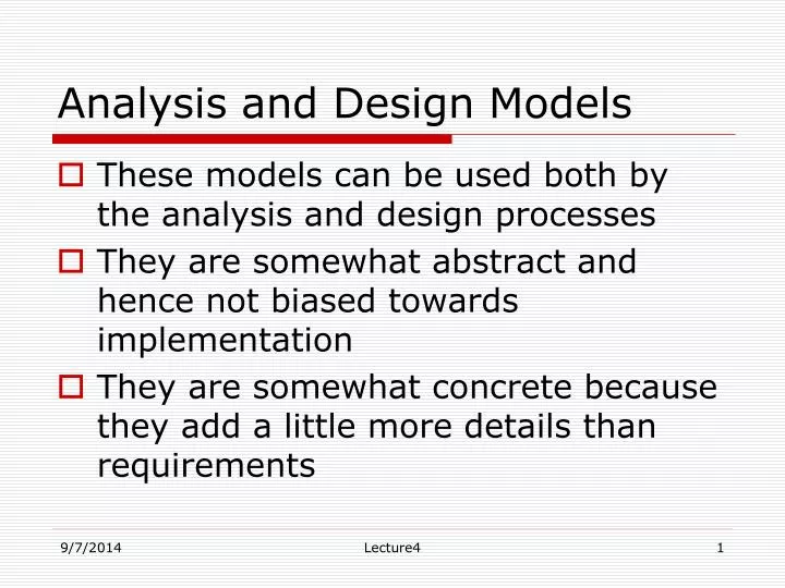
Analysis and Design Models. These models can be used both by the analysis and design processes They are somewhat abstract and hence not biased towards implementation They are somewhat concrete because they add a little more details than requirements. Analysis and Design Models.

E N D
Analysis and Design Models • These models can be used both by the analysis and design processes • They are somewhat abstract and hence not biased towards implementation • They are somewhat concrete because they add a little more details than requirements Lecture4
Analysis and Design Models • Models help the analyst to understand the functionality of the system and models are used to communicate with customers • Different models present the system from different perspectives • External perspective showing the system’s context or environment • Behavioural perspective showing the behaviour of the system • Structural perspective showing the system or data architecture Lecture4
Weaknesses • They do not model non-functional requirements • They do not usually include information about whether a method is appropriate for a given problem • They may produce too much documentation • The models are sometimes too detailed and difficult for users to understand Lecture4
Analysis and Design Models Data Object Descriptions Process Specifications Entity Relationship Diagrams Data Flow Diagrams Data Dictionary State Transition Diagrams Control Specifications Lecture4
Data Dictionaries • Data dictionaries are lists of all of the names used in the system models. Descriptions of the entities, relationships and attributes are also included • Advantages • Support name management and avoid duplication • Store of organisational knowledge linking analysis, design and implementation Lecture4
Models • All the three models use a data dictionary • a collection of data objects in the application domain • Entity-Relationship Diagrams (ERD) • a diagrammatic description of data objects • Data Flow Diagrams (DFD) • indicate the processes involved and data flowing between the processes • State-Transition Diagrams (STD) • a behavioral model of the system; indicates the states of the system/data objects Lecture4
Data Objects Object: something that is described by a set of attributes (data items) and that will be manipulated within the software (system) • Each instance of an object (e.g. a book) can be identified uniquely (e.g. ISBN#) • Each plays a necessary role in the system i.e., the system could not function without access to instances of the object • Each is described by attributes that are themselves data items Lecture4
Types of Objects • External entities (printer, user, sensor) • Things ( reports, displays, signals) • Occurrences or events (interrupt, alarm) • Roles (manager, engineer, salesperson) • Organizational units (division, team) • Places ( manufacturing floor) • Structures (employee record) Lecture4
Data Object • A composite entity holding data • different from primitive entities that hold only one value • an identification card is a data object • an identification number is not a data object • different from objects in object-oriented approach • data objects do not have encapsulated functions Lecture4
Data Object Description • A data object consists of • a unique identifier • a set of attributes • a set of relationships with other data objects • Example - Chair • identifier: part # is AZ12876 • attributes: color is blue, type is “no-arm”, … • relationships: “is placed” in a “computer room” Lecture4
Relationship Relationship – indicates “connectedness”; a fact that must be “remembered” by the system and cannot or is not computed or derived mechanically • Several instances of a relationship can exist • Objects can be related in many different ways Lecture4
Cardinality of relationships between data objects • One-to-one • a car has a steering wheel • One-to-many • a person has several cars • Many-to-many • a library user may read several books and a library book might be read by several users Lecture4
Modality of relationships between data objects • True or false (1 or 0) • Each data object in the relationship has a modality • Two data objects participating in the same relation may have different modalities • True (or 1) indicates that the relationship is MANDATORY in that application • A relationship between “repair work” and “vehicle”. True from “repair work”. • False (or 0) indicates that the relationship is OPTIONAL in that application • The relationship between “repair work” and “vehicle” is optional as far as “vehicle” is concerned because a vehicle may or may not have any repairs Lecture4
Notations and semantics of entity-relationship diagrams Relationship Specialized Relationship Lecture4
ERD – Example 1 (Data Dictionary) • Restaurant • Id: <restaurant name and address> • Attributes: food items prepared, special for the day, preferred customers list, … • Relationships: <<fill in later>> • Food • Id: <item name> • Attributes: color, type, taste, price, … • Relationships: <<fill in later>> • Customer • Id: <customer name> • Attributes: preferred food items, … • Relationships: <<fill in later>> Lecture4
Food n n Prepares Eats 1 m Restaurant Customer Pays n m ERD – Example 1 (ERD diagram) • Modality: thick (small) bar indicates mandatory; circle indicates optional • Cardinality indicated by the number closer to the entity Lecture4
ERD – Example 1 Explanation • Relationship – Prepares • Entities – Restaurant and Food • Cardinality for Restaurant is 1 One restaurant prepares many • Cardinality for Food is n food items • Modality for Restaurant is 1 Restaurant must prepare • Modality for Food is 1 food items • Relationship – Eats • Entities – Customer and Food • Cardinality for Customer is n Many customers eat several • Cardinality for Food is m food items • Modality for Customer is 0 • Modality for Food is 0 Lecture4
ERD – Example 1Explanation (continued) • Relationship – Pays • Entities: Customer and Restaurant • Cardinality for Customer is m There are customers • Cardinality for Restaurant is n for a restaurant • and there are several restaurants that • a customer visits • Modality for Customer is 0 Customer not interested in • Modality for Restaurant is 0 visiting any restaurant and • Restaurant does not have • any customer Lecture4
Default notations in ERD diagrams • If a cardinality is not specified, it is assumed to be 1 (ONE). • If a modality is not specified, it is assumed to 0 (ZERO). • Specialized relationships do not have any names • Specified by empty diamonds • See the next example Lecture4
ERD – Example 2 (Data Dictionary) • Dealer • Id: <Dealer name and address> • Attributes: list of automobiles, list of customers, … • Relationships: <<fill in later>> • Customer • Id: <customer name and address> • Attributes: list of automobiles interested, … • Relationships: <<fill in later>> • Automobile • Id: <vehicle ID number> • Attributes: color, model, year, … • Relationships: <<fill in later>> Lecture4
ERD – Example 2 (ERD Diagram) Lecture4
ERD – Example 2Explanation • Relationship – Pays • Entities – Dealer and Customer • Cardinality for Dealer is 1 One dealer and many customers • Cardinality for Customer is n • Modality for Dealer is 0 No dealer for a particular • Modality for Customer is 0 customer and no customer for a • particular dealer • Relationship – Buys • Entities – Customer and Automobile • Cardinality for Customer is 1 One customer buys many • Cardinality for Automobile is n automobiles • Modality for Customer is 0 No customer is buying • Modality for Automobile is 0 an automobile, and there may • not be any automobile for a customer Lecture4
ERD – Example 2Explanation (continued) • Relationship – Sells • Entities – Dealer and Automobile • Cardinality for Dealer is 1 One dealer sells many • Cardinality for Automobile is n automobiles • Modality for Dealer is 1 At least one dealer must be • Modality for Automobile is 0 there to sell, but there may • not be any automobile to • sell • Relationship – specialization (unnamed) • Entity Automobile is specialized into Car and Minivan • Every relation with Automobile is also applicable to Car and to Minivan Lecture4
ERD – Example 3Phone Book • Data Dictionary • Entity: User • Attributes: ?? • Relationships: uses a phone book • Entity: Phone Book • Attributes: Phone Diary and Appointment Calendar • Relationships: used by a user • Entity: Phone Diary • Attributes: Name, address, phone numbers, … • Relationships: none • Entity: Appointment Calendar • Attributes: Date, time, appointment, name • Relationships: none Lecture4
ERD –Phone Book Lecture4
ERD - Phone bookExplanation • Exercise • Write down the explanation of the relationships in the ERD for phone book. Lecture4
Building ERD • Level 1: model all data objects (entities) and their “connections” to one another • Level 2: model all entities and relationships • Level 3: model all entities, relationships and the attributes that provide further depth Lecture4
member item identification identification address name Example 4: ERD {0..10} {0..1} borrow Lecture4
Limitations of ERDs • Do not convey any information about the processes • Do not describe complex relationships • Attributes are part of data dictionary, but not shown in the diagram • Useful for data abstractions • mainly used in database modeling • Might be difficult for non-technical readers to understand Lecture4
Data flow diagrams • Modelling the system from a functional perspective • Tracking and documenting how the data associated with a process is helpful to develop an overall understanding of the system • Data flow diagrams may also be used in showing the data exchange between a system and other systems in its environment Lecture4
Data Flow Diagram (DFD) Lecture4
Semantics of DFD • External entity • External to the software; not created by the developers • Interacts with the software, but developer does not know (and cannot assume) its behavior • Following are the rules concerning external entities: • Each external entity has a unique name in the diagram; where there is more than one external entity with the same name, they are merged together to form a single logical external entity. • An external entity can send or receive data. • An external entity can only send control, but cannot receive control from the rest of the diagram; i.e., only the external entity can invoke some functionalities in the diagram, but not in the other way. • An external entity may not be connected to another external entity directly. This is because an external entity is (of course) external to the software under development and hence the communication between the two external entities is not under the control of the software. Lecture4
Semantics of DFD • Process • Represents an activity or a group of activities to be developed • Similar to procedure or module in a program • The rules given below govern the use of a process: • Each process in a data flow diagram must have a unique name. If more than one process has the same name, then all these processes are merged together to form one single logical process. • Self-looping arrows are not permitted in data flow diagrams (even though they are meaningful in the final implementation). Lecture4
Semantics of DFD • Data Store • Passive entity • Used to store and retrieve data • No need to specify its format in DFD • A data store is governed by the following rules: • A data store is uniquely labeled. If more than one data store exists with the same name, then they are all merged together to form one single logical data store. • A data store can be connected to a process or to an external entity through a data flow arrow only; hence, there should be no control flow arrows connected to a data store. • A data store may not be connected to another data store directly. Lecture4
Semantics of DFD (continued) • Data Flow • Carries data between • pair of processes • an external entity and a process • an external entity and a data store • a process and a data store • Control flow • Used by a master to invoke a slave • Used between • From an external entity to a process • From one process to another Lecture4
Data Flow Arrow • Data flow arrows are governed by the following rules: • A data flow arrow must be labeled; the label indicates one or more names corresponding to the data passed. • It is a good practice to choose labels that are meaningful in the application domain. Sometimes, the diagram may become messy if you choose the same names as in the application domain (example - supervisor, project manager, technical leader, and so on), particularly when there are so many elements in the diagram and the names are long. In such situations, you may use simple or short labels and give the actual meaning of the labels separately, under the title "Legend". Neither the labels nor their meanings have any fixed format or representation or type information. They simply stand for the data being exchanged. Lecture4
Control Flow Arrow • The following rules are applied to control flow arrows: • A control flow must connect either two processes or connect an external entity and a process. • If it connects two processes, the process at the head of the arrow is invoked/used by the process at the tail end of the arrow. • If it connects an external entity and a process, then the external entity must be at the tail end of the arrow, meaning that the external entity invokes the process. • A control flow is not labeled. • There cannot be more than one control flow between the same two processes or between the same pair of an external entity and a process. Lecture4
DFD – Example 1 Home alarm system A computerized home alarm system includes a front panel. This front panel has a keypad and a display unit. Users can configure the system with passwords. All interactions with the alarm system are done through the front panel.When an intruder enters the home, the sensors (part of the alarm system hardware) identify the intrusion and the alarm system raises an alarm. At the same time, the alarm system automatically dials one or more predefined numbers stored in the configuration. Lecture4
DFD Example 2: A Library A library maintains a collection of items. The information about all items is kept in a database. The information about users is kept in another database. A user of the library can borrow an item, return an item and reserve an item. Assume that there is no limit to the number of items a user can borrow. Develop a DFD for this problem. Lecture4
DFD – Example 2: A Library • Data Dictionary • Entity: User • Id: user name or user id • Attributes: name, … • Entity: Item • Id: call number • Attributes: call number, title, year of publication, … • Entity: User Database • Id: Name of the database • Attributes: user entries Lecture4
DFD – Example 2: A Library (continued) • Data Dictionary (continued) • Entity: Item Database • Id: Name of the database • Attributes: Item entries • Entity: Librarian • Id: name or employee id • Attributes: name, … Lecture4
User database User id User details Updated user details User id User id Update user details Verify user User Librarian Return date Call number Call number Issue item Verify item Return date Item details Call num Issued item Updated item details Item Database DFD – Library -- “Borrow” Lecture4
DFD – Library - Exercise Expand the DFD for the library shown in the previous slide by adding the processes and dataflow corresponding to the two activities “reserve an item” and “return an item”. Lecture4
a b P x y level0 c p2 a f p1 g b p4 d p5 e p3 level 1 Data flow hierarchy Lecture4
Data Flow Diagram – Example 1 Lecture4
Data Flow Diagram – Example 2 Lecture4
Data Flow Diagram – Example 3 Lecture4
State machine models • Model the behaviour of the system in response to external and internal events • Show the responses to a stimuli so are often used for modelling real-time systems • M=(S,I,T, F, s0), where S is a finite nonempty set of states I is a finite nonempty set of inputs T is a function from S X I to S called the transition function s0 S is the initial state F is a finite set of terminal states Lecture4
State Transition Diagrams • Graphic representation of a state machine • Nodes represent states • Arrows(directed edges) represent transitions • The annotations on the edges represent events and actions Lecture4