Download
1 / 97
1.03k likes | 1.42k Vues
A Brief Introduction to Engineering Graphics. Will Durfee & Tim Kowalewski Department of Mechanical Engineering University of Minnesota. Opening comments. Engineering graphics is the method for documenting a design

E N D
A Brief Introduction toEngineering Graphics Will Durfee & Tim Kowalewski Department of Mechanical Engineering University of Minnesota
Opening comments • Engineering graphics is the method for documenting a design • Mechanical engineering students must be familiar with standards of engineering graphics as it is expected in industry • This set of slides introduces some of the basics, but is not comprehensive • For more, see • Engineering Graphics section on the Resources page of the course ME2011 website • Any engineering graphics textbook
Documenting a part requires... 1. SHAPE 2. SIZE 3. MATERIAL 4. TOLERANCE 5. FINISH
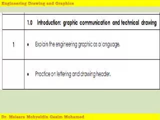
Engineering drawings • Universal language • Conventions (drawing grammar) simplify communication; your drawing is at risk if you defy • CAD packages make formal drawing easy…if you follow the conventions • The machinist will laugh at you behind your back if you show up with a non-standard drawing
Top Right Front Multiview drawings TOP RIGHT SIDE FRONT “3rd angle projection”
Top Right Front Multiview drawings TOP Views MUST align RIGHT SIDE FRONT “3rd angle projection”
Top Right Front Multiview drawings TOP Views MUST align RIGHT SIDE FRONT Rotate the part to the right (Europe) “3rd angle projection” You walk around part to the right (US)
The Glass Box: Bertoline, Engineering Graphics
Alignment & Orientation are preserved… Bertoline, Engineering Graphics
Basic lines (the “alphabet of lines”) Object line Hidden line Center line Dimension line
Interpreting Center Lines Enough Info? Enough Info?
OR THIS Centerlines imply symmetry, NOT revolution per se
HERE, ONLY 2 VIEWS NEEDED (Correct drawing)
FRONT FIND THE MISTAKES!
A A SECTIONS YES NO
Working with person sitting next to you copy this and draw the TOP VIEW
Possible Geometries Working with person sitting next to you copy this and draw the TOP VIEW
Working with person sitting next to you, sketch the Section View
OK OK Correct Section Views
Wrong Wrong Working with person sitting next to you, Find the MISTAKES
Working with person sitting next to you, sketch the Section View
REVOLVED SECTION Preferred “True” section
DIMENSIONING 1. SHAPE2. SIZE3. MATERIAL4. TOLERANCE AND FINISH
3 5 Dimensioning • Conventions exist for choice and placement • Not too many and not too few • Never should measure off drawing with a ruler 5 3
5 5 3 3 3 2 5 5 Under/Over Dimensioning
5 5 3 3 2 3 5 5 Dimensioning rules: …find the mistakes.
5 5 3 3 2 3 5 5 Dimensioning guidelines 1. Don’t overdefine or underdefine the object. [MOST IMPORTANT] 2. Dimension to the visible contour or shape of the feature/ Don’t dimension to hidden lines. 4. Don’t dimension to object lines (model edges), use extension lines. 5. Don’t overlap a dimension and the model. Place dimensions away from the model’s surface. 6. Don’t cross extension lines if possible. 7. Group dimensions when possible unless it become difficult to read. 8. Place dimensions on the side of the view were adjacent views exist (for easy referencing).
6.0 6.0 Design Detail½” thick aluminum block Which is more expensive: A or B and why? A B 4.0 4.1
6 6 2 4 2 2 6 6 Dimensioning Choices& Design Intent If change width of block to 8, what happens to the hole location? B A
Lettering: 1 or 2 directions only OK OK NO
All on one side YES NO
0.75 R 0.125 0.25 Dimensioning Rounds Place dimension on view that shows the circle Show diameter rather than radius
TOLERANCES www.efunda.com/processes/machining/drill.cfm www.efunda.com/processes/machining/drill_press.cfm
Tolerances • Matter because parts cannot be made to an exact dimension • Must specify dimension tolerance so that every part A fits every part B • Higher tolerance = higher cost • A ½ inch hole made on an ordinary drill press gives you a hole in the range 0.496 to 0.504 (+/- 0.004). For higher precision, drill undersize and use a reamer…but it will cost you more and take longer to fabricate.
½ inch drill bit: +/- .0040 ½ inch reamer: +.0003, -.0000
D 5 8 1.7 9.6 LEGOS ! ABS plastic • You can combine six 8-stud bricks of the same color 102,981,500 different ways • 91% of all households with children in Denmark own LEGO products • During the period 1949-1990, 110,000,000,000 (110 billion) LEGO elements were molded • Bayer Corporation's Polymers Division is the official supplier of ABS plastic to the LEGO group. • Exact specifications of the Bayer resin supplied to the LEGO Group are a closely held secret. • Dimension tolerance of mold is 0.005 mm (0.0002 inch)!
Tolerance stack-up What is min and max height of stack? 14.7515.25 ? 3.0 ± .05 5 high stack