Download
1 / 21
210 likes | 323 Vues
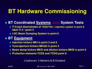
Hellenic Contribution to the LHC Hardware Commissioning. Rachel-Maria Avramidou On behalf of the Hellenic Team. The team. 1 physicist (PhD), 1 computer scientist, 3 computer engineers, 7 electronics engineers. Introduction to LHC. Basic layout

E N D
Hellenic Contribution to the LHC Hardware Commissioning Rachel-Maria Avramidou On behalf of the Hellenic Team
The team 1 physicist (PhD), 1 computer scientist, 3 computer engineers, 7 electronics engineers
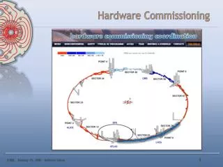
Introduction to LHC Basic layout 8 sectors (~3.3 km): arcs and straight sections (~528 m) P1: ATLAS detector P2: ALICE detector P3: Collimation system to capture off-momentum particles P4: Radio Frequency superconducting acceleration cavities (400 MHz) P5: CMS detector P6: Beam abort systems for the beams to be extracted safely and deposited onto external dump (absorb the stored energy) P7: Collimation systemto control the beam halo P8: LHCb detector Two-ring superconducting pp collider of 27 km circumference The dipoles must operate at 8.3 T and be cooled in superfluid helium at 1.9K
LHC Status • Installation of LHC almost completed • Emphasis moves from installation to commissioning • The cool down of the sector 7-8 to helium liquid temperature recently completed • First beam injection (450 GeV/c) is foreseen before the end of the year to debug the machine and detectors • First physics run at 7 TeV per beam in 2008
Team contributions • Development of the Test Bench that assures the quality of Cryogenics Electronics • Debugging of Cryogenic Instrumentation in the tunnel • PVSS (software development and graphics) • Communication and coherence tests (CIET, PLC+SCADA, troubleshooting) • Installation, configuration, initialization and troubleshooting of the electronics units for the positioners • Testing and troubleshooting for the cryogenic sensors, cards and cables with the Mobile Test Bench (MTB) • Cryogenics electronics for the radio frequency system (design, installation, etc) • Sensor cabling (deployment, connection, extensions) • Sector inspection • Preparation, labeling and installation (connections) for the crates. • Labeling (crate positions, IFS cables, QV valves, sensor cables etc) • Measurements with gauge level (helium level) and data analysis • ATLAS (A. Koumparos, G. Theodoropoulos, C. Vottis) • CMS (K. Anastasopoulos, F. Karagiannis, I. Polychroniadis)
Cryogenics instrumentation installation in the tunnel Instrumentation crates (~800) are being installed and connected to the LHC. They contain electronic cards that measure temperature, pressure and cryogenic liquid level.
Test Bench • Development of the Test Bench that assures the quality of all electronics for Cryogenics (Temperature, Pressure, He Level Transducers) in their manufacturing factory. This Test Bench consisted of a means of debugging the pre-series designs of the electronics in order to conclude to their final models that went to mass production. • Debugging of Cryogenic Instrumentation (electronics, cables, sensors) after their installation in the LHC tunnel.
Mobile test bench • Useful tool for the electronics troubleshooting • Consistency test • Card test (simulation) • Instrument test Examples of problems: not connected and wrongly connected cables (machine side), blown fuses, bad cables, broken connectors, missing connections
Digital Valve Positioners for QRL Installation, configuration, initialization and troubleshooting of the electronics units • Intelligent positioners (communicating by Profibus PA) used to adjust and control the pneumatic actuators of the cryogenic control valves of the QRL (cryogenic distribution line) • The electronic unit in radiation protected areas • The pressure radiation block close to the valve (potentiometer reads the stem position, 2 piezo-valves pressurise and depressurise the pneumatic actuator) rack front rack back Profibus DP/PA couplers Drawers with intelligent valve positionners
Cryogenics Control System • Cryo Control System Provides the measurements from the cryogenics instrumentation (Temperature, Pressure, Level and QV, PV valves). Gives orders to the heater actuators coming from the control system PLC and commands to protect the Level measurements electronics • CIET: Cryo Instrumentation Expert Tool Provide all the info coming from the signal conditioners/electronic boards to the cryogenics experts by means of an expert tool based on PVSS
PVSS • The SCADA system used in UNICOS • Provides the supervision layer for the cryogenics instrumentation • The supervision layer is designed in PVSS
Contribution to PVSS • Design and maintain the supervision panels
Contribution to PVSS • Develop the necessary software tools for fast and efficient maintenance.
Team’s web page The webpage was developed during summer 2006 by A.Koumparos as a mean to offer some information to the public about our contribution to the LHC and the other experiments. http://cern.ch/hellenicomm/
Conclusions • Working at CERN is a unique experience for young scientists and engineers • The team has been adjusted quickly to the CERN environment, has gained experience, has increased speed and efficiency and is highly appreciated by CERN group. • Many thanks to all people who made this project a reality • Some more support by the greek administration concerning relevant issues would have been very helpful
Controls architecture for LHC full sector Full Sector All valves in alcoves accessed through Profibus All tunnel instruments accessed through WorldFip
Cooldown • 2 weeks of flushing • Electrical quality assurance test • 2 weeks from ambient to 80 K • Second electrical quality assurance test • 1 week from 80 K to 4.2 K and then to 1.9 K