Download
1 / 24
240 likes | 356 Vues
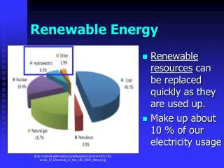
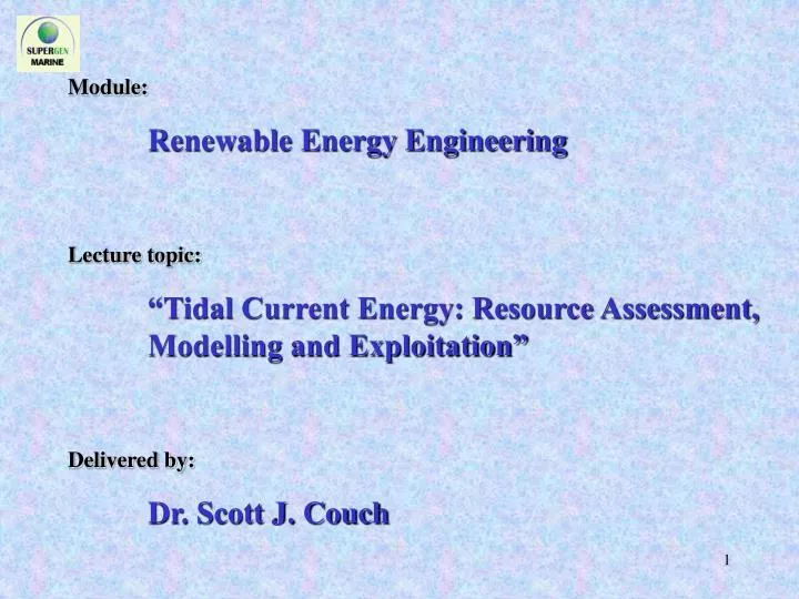
Module: Renewable Energy Engineering Lecture topic: “Tidal Current Energy: Resource Assessment, Modelling and Exploitation” Delivered by: Dr. Scott J. Couch. Relevant topics covered by Prof. Bryden: Tide generation by the Earth-Moon-Sun system

E N D
Module: Renewable Energy Engineering Lecture topic: “Tidal Current Energy: Resource Assessment, Modelling and Exploitation” Delivered by: Dr. Scott J. Couch
Relevant topics covered by Prof. Bryden: • Tide generation by the Earth-Moon-Sun system • Tidal interaction with land and resulting dynamics • Energy available in tides • Technologies proposed for tidal energy extraction • 1-d modelling of energy extraction
Generic tidal regime classification: • Offshore deep ocean • Unbounded nearshore coastal ocean • Tidal streaming • Hydraulic current • Resonant systems • M2 tidal component (amplitude (m) & phase (degrees))
Requirements for renewable energy production: • Energetic and persistent tidal resource • Currently proposed technologies limited to 50 metres maximum depth • Access to the local or national grid • Regimes 3, 4 and 5 are therefore most relevant for exploitation
< 0.25 m/s 0.25 – 0.50 m/s 0.50 – 0.75 m/s 0.75 – 1.0 m/s > 1.0 m/s • Tidal streaming example (amplification of tidal velocities through a flow constriction). • Similar principles to the so-called ‘venturi effect’, but important physical differences
Hydraulic current example: (Naruto Strait, Japan): Source: http://133.31.110.195/D/inetpub/wwwroot/www/text-English/page-07/page-07-01naruto.htm
Images: http://en.wikipedia.org Resonant channel example • Bay of Fundy (Minas Basin): recorded tidal range of 17 m • Gradual tapering and shallowing constricts the tidal flow • Standing wave established: A standing wave arises when the incoming tidal wave and an earlier, reflected tidal wave constructively interfere. The interaction can create very large tidal amplitudes and associated tidal currents.
Numerical Modelling Background: • Large numerical modelling community focussed on tidal flow modelling has spun up since the early two-dimensional models of the 1950’s and 1960’s. • Typical application of these models is very diverse: • Governing equations are applied on a grid structure using a finite-difference, finite-element or finite-volume approach. This produces a regular array of flow velocity and surface elevation data throughout the tidal cycle (output at selected intervals).
η d h U V Δy Δx Temporal Streamwise Cross-stream Coriolis Pressure Bed friction term momentum term momentum term term gradient term term (i) (ii) (iii) (iv) (v) (vi) Wind stress term (zero-equation turbulence model) - eddy viscosity term (vii) (viii) Numerical Modelling: Formulation GOVERNING (SHALLOW WATER) EQUATIONS: Conservative form of the continuity equation: Conservative form of the x-directed momentum equation (momentum flux):
Application of tidal numerical models in Renewables • Numerical models can be used to simulate a site of interest for energy harvesting with a high degree of accuracy . The bugbears of this approach are: • Generating a solution requires reliable data to generate the model driving conditions at an upstream location. • Simulating a real site with any degree of accuracy requires a significant investment of time. • The availability of an experienced modeller and analyst. Beware, as with all complex problems, numerical modelling or otherwise, rubbish in = rubbish out! • Models and physical understanding need further development to accurately simulate the impact of energy harvesting on the system
Examples of research application of numerical models in the marine renewables context • Generic properties of all idealised cases considered: • Uniform depth, d = 35 m; friction coefficient, n = 0.025 sm-1/3; Coriolis parameter, f = 0; wind stress, Wx Wy = 0 ms-1. • Simulations spun up from a cold start over an equivalent quarter tide (amplitude 3.5 metres), then boundary conditions maintained at steady state. • Cell size, x = y = 80 metres. • Energy extraction per cell assuming swept area of 20 metres, lateral device spacing of 2 diameters, peak delivery of 750 kW per device and overall conversion efficiency of 25% = 6MWpower extracted from the flow per cell.
Pseudo 1-d tests: • 9.6 km long channel, 80 m wide (1 cell) – applying 2-d code. • Two test-cases: • 1st with no energy extraction • At steady state frictional losses balanced by a pressure gradient to produce typical ‘friction slope’ effect • 2nd with 6MWpower extracted from the flow at the mid-point of the domain. • At steady state energy extraction balanced by a pressure gradient • ‘Friction slope’ effect from case 1 still apparent but dwarfed by impact of energy extraction on the system. • Depth-averaged flow velocities increase downstream of extraction site through the continuity equation to balance head loss.
2-d ‘blockage’ idealised tests: • 9.6 km x 4.8 km channel. • Idealised island located • in centre of the channel. • Three test cases: • 1st with no energy extraction. • 2nd with 6MWpower extracted from the flow per cell along the y-axis centreline in both channels. • Results broadly similar to the pseudo 1-d test cases. • 3rd with 6MWpower extracted from the flow per cell along the y-axis centreline of the ‘upper’ channel only. • Overall flow velocity reduced in the upper channel and increased in the lower channel • Significant upstream and downstream flow asymmetry (vortex shedding downstream).
0.0 – 1.0 ms-1 1.0 – 2.0 ms-1 2.0 – 3.0 ms-1 3.0 – 4.0 ms-1 > 4.0 ms-1 A B C D T T Energy extraction site S S A B C D Depth-averaged flow velocity vector map for 2nd 2-d test case (both channels exploited). Discharge per metre width at four representative cross-sections.
0.0 – 1.0 ms-1 1.0 – 2.0 ms-1 2.0 – 3.0 ms-1 3.0 – 4.0 ms-1 > 4.0 ms-1 A B C D T T S S A B C D Energy extraction site Depth-averaged flow velocity vector map for the 3rd 2-d test case (only northern channel exploited). Discharge per metre width at four representative cross-sections.
S S T T Along channel depth variation for representative sections ‘S’ (1st 3 lines) and T (last line)
0.0 – 1.0 ms-1 1.0 – 2.0 ms-1 2.0 – 3.0 ms-1 3.0 – 4.0 ms-1 > 4.0 ms-1 0.0 – 0.25 ms-1 0.25 – 0.5 ms-1 0.5 – 0.75 ms-1 0.75 – 1.0 ms-1 > 1.0 ms-1
3-dimensional analysis Comparison of 3-d stream-wise flow development with varying levels of kinetic energy extraction. Mid layer (a) elevation profiles, (b) layer integrated velocity profiles through the water column for σ-layer 5 (of 10). Bed layer Surface layer Layer integrated velocity profiles through the water column, (c) σ-layer 1 (bottom), and (d) σ-layer 10 (top)
Representative vertical velocity profiles across the domain length indicating influence of energy extraction (set at 50%) • Minimal upstream effect (overlapping profiles). • At extraction site, (i) increased flow velocity near the sea-bed and surface, (ii) decrease in flow velocity in layers where energy is extracted, and (iii) enhanced shear between σ = 0.65 and σ = 0.75, and reduced shear between σ = 0.15 and σ = 0.25. • Downstream flow velocity is slowly re-distributed towards upstream values.
Modelling the Energy Extraction Process: The impact of energy extraction on the tidal system (e.g. resource, environment (physical, biological and chemical)) is not well understood. A large focus of Professor Bryden’s research group is in addressing these issues. In previous lectures, the formula for deriving the kinetic energy in a moving flow of water was presented This formulation is correct from first principles, and is correctly applied when describing the incident energy available to a device for extraction. Initial attempts by our research group to use this formulation to describe the impact of extraction on the tidal resource surprised the research community ……. ρ is the fluid density, A the swept area and U the fluid velocity
h1 h2 u1 u2 Section 1 energy extraction Section 2 Two outcomes from modelling analysis made us question the use of the kinetic energy flux when considering the response of the tidal system as opposed to the device performance: friction slope h1 h2 u1 u2 Section 1 NO energy extraction Section 2 • Assuming a uniform width channel, u1h1 = u2h2, therefore u2 > u1, and hence the kinetic energy is increased downstream. • Sensitivity analysis demonstrates that morethan 100% of the raw available kinetic energy can be extracted from the system! • ……………….
These findings appear counterintuitive. Dynamic and non-linear effects associated with tidal flows ensure that life is not quite as simple as we would like, or that previous research in the field had suggested! Research we are currently pursuing is having better success at accurately simulating the impact of energy extraction on the system, and is therefore leading to enhanced understanding of the underlying physics of the effect of energy extraction on the tidal system, and on flow – device interactions. The physical response of tidal flow to energy extraction indicates that the kinetic energy in the system is notnecessarily the only consideration when quantifying the available resource, even although it is only the kinetic energy in the system that the device will directly interact with.
Context • Although currently an unexploited energy source, a number of competitive advantages are offered by the harvesting of clean, sustainable energy from tidal currents. • Continued research and development effort is required to: • Improve device efficiency, reduce costs and understand maintenance and reliability issues. • Enhance understanding of the short and long term physical, biological, chemical and social impact of harvesting tidal current energy. • Provide regulatory guidance and interface with the relevant stakeholders, be they device developers, energy carrier and supply companies and ultimate end-user. • ……………
In the specialized area of resource assessment and modelling, the scientific goal is to develop existing systems which are currently able to accurately predict the pre-development tidal flow development (see accompanying image), to be able to produce realistic simulations of the flow development, energy potential and impacts on the various related systems when energy harvesting facilities are installed Image characterising the tidal current and therefore kinetic energy potential of Yell Sound in the Shetland Islands (produced by colleagues based at The Robert Gordon University).