Download
1 / 17
170 likes | 385 Vues
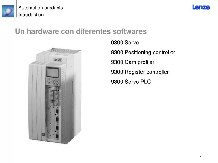
Un hardware con diferentes softwares. 9300 Servo 9300 Positioning controller 9300 Cam profiler 9300 Register controller 9300 Servo PLC. Datos Tecnicos: Drive PLC - Conectores. Entradas Digitales / salidas: 8 / 4 Entradas Analog / salidas : 3 / 1 Bus de Campo: AIF-port System bus

E N D
Un hardware con diferentes softwares • 9300 Servo • 9300 Positioning controller • 9300 Cam profiler • 9300 Register controller • 9300 Servo PLC
Datos Tecnicos: Drive PLC - Conectores • Entradas Digitales / salidas: 8 / 4 • Entradas Analog / salidas : 3 / 1 • Bus de Campo: AIF-port System bus • Expandible con Módulos enchufables
Datos tecnicos: Drive PLC - Modulos de Extension • Modulo Extensión 1: • Digital inputs: 6Digital outputs (1A): 4Digital outputs (2A)): 2 • Modulo Extensión 2: • Digital inputs: 14Digital outputs (1A): 8 • Modulo Extensión 3: • Digital inputs: 8Digital outputs (1A): 4Analog inputs: 2Encoder input TTL, HTL,500kHz: 1
Datos Tecnicos: Modulos AIF (automation interface) • Son Identicos para el Servo PLC y Drive PLC: • LECOM A/B (RS232/RS485) • LECOM-LI (Fiber Optic) • Interbus, Interbus-Loop • Profibus-DP • Systembus • DeviceNet • CANopen • FP-Interface (RS232, free programmable) • Keypad
Datos tecnicos: Modulos AIF (automation interface) • Son identicos para el Servo PLC y Drive PLC: • LECOM A/B (RS232/RS485) • LECOM-LI (Fiber Optic) • Interbus, Interbus-Loop • Profibus-DP • Systembus • DeviceNet • CANopen • FP-Interface (RS232, free programmable) • Keypad
CAN Bus • Conexión mediante conectores enchufables • Cable: pares trenzados, apantallados • Máximo numero de nodos CAN: 63 • Se puede acceder a todos los códigos Lenze y al programa del PLC
PLC Entorno de Desarrollo • Programacion mediante Soft • Drive PLC Developer Studio.Propiedades Basic Prof. • Lenguajes:- IL x x- LD x x- FBD x x- ST x- SFC xMonitoring x xDebugging x xVisualisation xParameter tool x xRecipe Management x x
IEC 61131-3 Lenguajes de programacion • Programacion mediante 5 lenguajes diferentes con normativa IEC 61131-3. • Todos los valores y variables se pueden visualizar Online.
Conversion de lenguajes IEC 61131-3 • Un objeto programado en ST, IL, FBD ó LD puede ser convertido a IL, FBD ó LD.
Codigos Servo PLC / Drive PLC • Es posible general codigos de usuario • Es posible acceder a estos codigos via system bus ó en AIF-port (e.g. por keypad, Profibus…).
Templates aplicaciones • Speed control • Torque control • DF-Master/Slave • Positioning • Winder • Cam
Documentacion y ayuda Online • Una ayuda Online esta integrada en el entorno de programacion. • La ayuda Online contiene links de acceso a la documentacion, para recibir mas informacion de las funciones.
Estructura de la aplicacion Target System Servo PLC Decentralisation Task Task Multitasking Program Program Functionblock Function Functionblock Function Function
Tarea Ciclica Control power on • Al poner en marcha el PLC se inicializan las variables internas del programa, despues se siguen siempre los siguientes pasos: Initialize the non remanent variables, counter, timer and the output image. • 1. Las entradas fisicas son copiadas en la imagen de entradas. • 2. La logica PLC se va ejecutando usando las entradas respectivamente de la imagen de salida No hay actualizacion de la imagen durante este paso. • 3. La imagen de salida se copia a las salidas fisicas. Save inputs in input image Inputs PLC program execution Actualize timer Control interface Execute PLC program command by command Write output image to outputs Outputs
Pantallas HMI • Portfolio de HMI:2 Pantallas de texto1 Pantalla grafica2 Pantallas tactiles • Representacion de textos, dibujos, barras graficas, y graficos animados. • Recetas • Display de alarmas y mensajes • Comunicacion via System bus • Funcion de teclas programable • Proteccion mediante Password
Herramientas de configuracion • Global Drive Control (GDC) Dispone de herramientas para configuracion, ajuste de parametros y visualizacion, para una mas facil comprension y diagnostico.
Modulo de extension IO • El modulo de extension I/O dispone de entradas y salidas digitales adicionales. • Cada uno de los terminales se puede configurar como entrada o salida.