Download
1 / 22
240 likes | 524 Vues
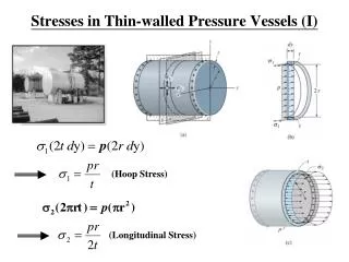
HESSE AND RUSHTON METHOD. Pressure Vessels. SHELL THICKNESS. where t p = shell thickness (inch) P = Max allowable working pressure (psi) D = Inside diameter (inch) S = Max allowable tensile stress (psi) (Table 6-6) e = Efficiency of welded joint (Table 6-7)

E N D
HESSE AND RUSHTON METHOD Pressure Vessels
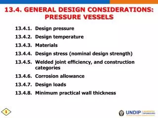
SHELL THICKNESS where tp = shell thickness (inch) P = Max allowable working pressure (psi) D = Inside diameter (inch) S = Max allowable tensile stress (psi) (Table 6-6) e = Efficiency of welded joint (Table 6-7) C = Corrosion allowance
SHELL THICKNESS Applicable if: 1. tp< 0.10D 2. tp> tmin
Allowable Stress Estimation S = Su x Fm x Fs x Fr x Fa Where Su = Minimum Specified Tensile Strength Fm = Material Factor Fm= 1 for Grade A material Fm= 0.97 for Grade B material Fm= 0.92 for Grade C material Fs= Temperature Factor (Use Table 6-7) Fr = Stress Relief (SR) Factor Fr = 1.06 When SR is applied Fa= Radiographing Factor Fa= 1.12 when Radiographing is applied and subsequent repair of defects
Stress Relief Factor Stress relieving is mandatory for: 1. tp > 1¼” 2. (For thinner plates) where D has a minimum value of 20 inches 3. ASTM A – 150 4. ASTM A – 149 (under certain conditions)
Radiographing Factor Radiographingis mandatory for: 1. ASTM A – 150 2. ASTM A – 149 (under certain conditions) 3. Lethal gases application 4. Nuclear Reactor applications
Sample Problem 1 A 12 in diameter S-2 Grade A steel has a working pressure and temperature of 500 psi and 300F respectively. Determine the type of weld to be used and plate thickness using Hesse and Rushton method. Assume zero corrosion allowance.
Sample Problem 2 Grade A S2 steel, butt welded pressured vessel for lethal gas application has an inside diameter of 20 inches. If the working pressure is 900 psi and the working temperature is 250ºF, what is the shell thickness of the vessel? (Use minimum corrosion allowance and Hesse and Rushton method).
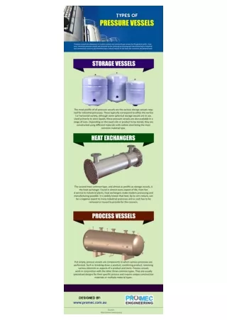
HEAD Configurations • Torispherical • most common type of head used and usually the most economical to form • The I.C.R = I.D of the head or less • between 90% to 95% of the I.D of the head • The I.K.R = 6% and 10% of the I.C.R of the head • The S.F = 10mm and 30mm
HEAD Configurations • 2:1 Semi-Ellipsoidal • deeper and stronger than a torispherical head • more expensive to form than a torispherical head, • but may allow a reduction in material thickness as the strength is greater • The I.C.R is 0.8 of the O.D of the head • The I.K.R is 0.154 of the O.D of the head • The S.F =10mm and 30mm
HEAD Configurations • Hemispherical • allow more pressure than any other head • most expensive to form • The depth of the head is half of the diameter.
HEAD Configurations • Shallow Head • commonly used atmospheric tanks • not suitable for pressure vessels • I.C.R =1.5 to 2.0 times the I.D of the head • I.K.R = 32mm, 51mm or 76mm (depending on the diameter and customer requirements) • The S.F =10mm and 30mm
HEAD Configurations • Cones for Pressure Vessels • The maximum internal apex angle for cones =120O • The I.K.R = 6% of the inside diameter of the vessel • The S.F =10mm and 30mm
HEAD Configurations • Flat. • A flat end with a knuckled outer edge • used as bases on vertical atmospheric tanks and lids for smaller tanks • The I.K.R =25mm, 32mm and 51mm • The S.F. = 10mm and 30mm
HEAD Configurations • Dish. • used for atmospheric tanks and vessels and for bulk heads or baffles inside horizontal tanks or tankers • Typically the I.C.R is equal to the diameter
HEAD THICKNESS Standard Ellipsoidal Hemispherical Standard Dished where L = crown radius in inches = Do – 6 Kr= knuckle radius = 0.06 Do
HEAD THICKNESS Standard Dished • Values for W or dished heads Kr/L W 0.06 1.8 0.07 1.7 0.08 1.65 0.09 1.6 0.10 1.55 0.11 1.50 0.12 1.47 0.13 1.44 0.14 1.41
HEAD THICKNESS Standard Dished • Values for W or dished heads Kr/L W 0.15 1.40 0.16 1.38 0.17 1.37 0.18 1.35 0.19 1.32 0.20 1.30 0.25 1.25 0.50 1.12 1.0 1.0
HEAD THICKNESS Flat Heads *Lap Welded w/ or w/o Plug Welds: *Single or Double V Butt Welded *Cut from Solid PlateStandardDished