Download
1 / 31
310 likes | 475 Vues
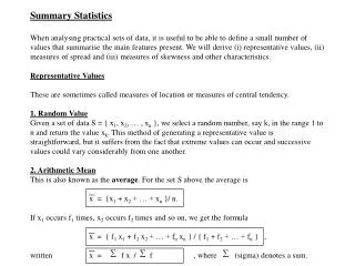
Universal Frequency Reference. Presented first at Gippstech 2012 V1.11 Glen English VK1XX glen@pacificmedia.com.au. Frequency reference system. Provides reference for any radio Low noise fundamental output 1Hz – 150 MHz Provides 30 mHz steps with 125 MHz clock

E N D
Universal Frequency Reference Presented first at Gippstech 2012 V1.11 Glen English VK1XX glen@pacificmedia.com.au
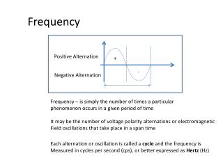
Frequency reference system • Provides reference for any radio • Low noise fundamental output 1Hz – 150 MHz • Provides 30 mHz steps with 125 MHz clock • Locked to GPS, auto holdover • Low Power (0.5-1.5W depending on power supply and output ) and 60 x 80 mm • Can be controlled/setup from PC
Implementation • Any GPS provides 1 pulse per second • Uses a DDS (direct digital synthesiser) • Free running TCXO or OCXO provides clock • Frequency of XO not critical • Many XOs do not have external V ctl- not required.
Basic Block diagram GPS Frequency counter XO CPU LPF and driver DDS
How DDS works (simplified) • Consists of a binary counter and an adder • The counter has a maximum value • The RF output is connected to the highest bit (MSB) of the counter. • A clock is input which every time there is a positive-going transition, a fixed value is added to the counter. • The amount added to the counter every ‘clock’ determines the how often the counter rolls over its maximum value
DDS counter • 4 bit binary counter being incremented with value of 3 every clock. • 0000,0011,0110,1001,1100,1111,0010,0101,1000,1011,1110,0001,0100,0111,1010,1101 • 4 bit binary counter being increment with value of 1 every clock • 0000,0001,0010,0011,0100,0101,0110,0111,1000,1001,1010,1011,1100,1101,1110,1111,0000,0001,0010,0011,0100
DDS cont • Example • Counter with max value of 100 • If a clock adds a value of 5 at 1MHz, what will be the rollover rate per second? • = (clock freq * step) / counter max (eq1) • = (1,000,000 * 5 ) / 100 • = 50,000 times per second.
DDS cont2 • This DDS : • can be clocked up to 400 MHz • Has a rollover value of 2^32=4,294,967,296 • Allows for very precise frequency steps if used as a synthesiser • Using (eq1) • 125e06 * 100,000 / (2^32) = 2910.383046 Hz • 125e06 * 100,001 / (2^32) = 2910.41215 Hz • Cosine lookup table is connected to the counter so that the DDS generates sine as well as square waves.
Frequency control • Precise DDS frequency steps allow us to use any source frequency for any output frequency • DDS has clock multiplier to further enhance flexibility. • But no control over frequency of source oscillator ? How do we lock this to the GPS ?
Frequency Counter • We count how many cycles of the fixed XO occur between 1PPS from the GPS • If 63,000,005 oscillator cycles are counted for each 1pps GPS pulse, the frequency must be 63,000,005 Hz • Now we know the frequency of the XO
CPU calculation • Think of DDS as a fractional divider (for the moment) • For 10 MHz output , we must program the DDS steps for (63,000,005 / 10,000,000) • Which is 6.3000005. which we can do…. • The XO frequency is measured every 2 seconds and the new ‘divisor’ (step) is applied to the DDS • Enables drift in XO to be compensated for • Averaging of different lengths are provided to enhance precision
Implementation • I figured this out when building WSPR DDS based exciters- I had odd frequency XOs available • PCB costs about $50 of bits depending on the type of oscillator used. • Better results with better quality oscillators -can work with $1 oscillator if does not change too much per update cycle. Proto used $4 125MHz TCXO. • Care taken to ensure no feedthru noises from digital controller into oscillator.
CPU job : Count clocks per GPS 0.5 pps pulse Update moving average Calculate actual XO frequency Calculate new Frequency Tuning Word Write to DDS
Outputs • PCB has: • 100mW RF driver • Opto isolated closures • Serial port for config/ctl • DAC output for audio tone generation • Can accept any oscillator 5 to 125 MHz input
Detailed Block diagram 9.9 MHz 0.5Hz 1Hz GPS /2 19.8 MHz 9.9 MHz GPS data Divider/1,2,4,8,16 Divider/1,2,4,8,16 CPU+counter XO serial 19.8MHz Multiplierx 1,4,5,6..20 13.2MHz LPF and driver DDS ~118.8MHz
Jitter Notes • Jitter performance of output limited to jitter performance of source XO • DDS output inherently has jitter equal to the DDS clock on output – this is why we low pass filter • On board filter design important to reduce jitter • Use highest DDS clock (by using on-chip multiplier) to ease filtering requirements • Jitter important when reference is multiplied up to 10 GHz.
Limitations • It is basically a frequency counter. • Longer counting times will yield more precision. • Compared with counting for one second , If the number of cycles over 10 seconds are counted, there is 10x the precision, as the ‘error’ produced is 10x what it would have been over 1 second. • Or average the 1 second results over 10 seconds (take avg of 10 numbers) , -same though bias in the number crunching must be removed.
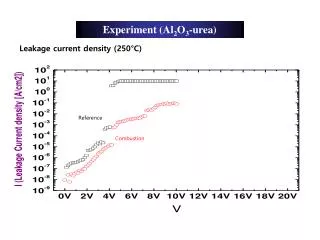
Oscillator limitations • Internal correction of some cheap TCXOs
Moving averages • Currently a moving average is used – • for each GPS 1pps pulse, the last n counts are added together and divided by n. • Update is therefore on the fly, but incapable of tracking changes faster than the filter length because current estimate is made up of last n values. • Thermal drift limit is imposed on the XO • This goes for all disciplined oscillators
Accuracy and Precision • Averaging improves error precision • Accuracy is based on 1pps GPS output • Count 1,000,000 cycles over 1 second • = 1Hz precision (1ppm) • Count 10,000,000 cycles over 1 second • = 0.1 Hz precision (0.1ppm) • Faster counters yield improved basic precision.
Improving precision • Higher precision per counter gate time (1 pps) yields better drift tracking capability. • Averaging improves precision but takes time • Sure we can get 0.00001 ppm if we wait a long time. • Some applications required good precision hold and absolute frequency accuracy is unimportant. • Some applications required high accuracy – IE blind netting on 10 GHz .
XO Thermals • Averaging with drifting XO just takes average of the frequency over the drift. Moving average is behind the time. • Yes more precision due to averaging. • But drift over averaging period reduced accuracy. • 10 MHz 1PPM XO (0-70C ) : if drifts 5 deg C • Drifts 0.0714ppm. A country mile
Drift calcs • 0.0714ppm. (5deg C)Not a country mile if over days. • If 10 MHz counter clock, 0.1Hz precision per 1 second gate. • = 0.1 ppm • Desired precision 0.01ppm = 10 sec averaging/counting. • Max thermal drift over 10 seconds is 0.7deg C.
Solution to drift problem • 2nd order predictor • The future events can be predicted from the previous events • Useful for warm up / warm down drift • Non linear change with time variations OK • Not useful for random drift
Drift 2 • Solution to short term random drift • Higher counter frequency • 30MHz counter clock = 0.0333 ppm/ sec • Vs 10 MHz clock = 0.1 ppm/sec • Averaging over long periods provides further precision but system can respond to short term drifts at high precision.
More basic precision by add clock multiplier 10 MHz (0.1ppm/sec) 100 MHz (0.01 ppm/sec) GPS 10 MHzXO X10VCO-PLL CPU/counter LPF and driver DDS
Next version • 48 bit DDS will provide 1mHz control steps at 10 GHz • Higher counter speeds (32 MHz)/slave osc. • Predictor improvement. • Need to port 128 bit math lib to micro. • On board GPS receiver opt. (adds about $50) • High Z square wave output. • More flexible power supply
Extras • Also functions as a stand alone FSK style beacon – WSPR implemented. • Can connect to PC to provide steps smaller than CAT control provides for doppler tracking.- FT817 10 Hz CAT steps example. • Radio will follow the reference frequency blindly. • Fast to get going (20 seconds after gps aq.) • Can do chirps, FM, PSK, FSK
DDS tutorial : http://www.analog.com/static/imported-files/tutorials/450968421DDS_Tutorial_rev12-2-99.pdf


![[Reference]](https://cdn3.slideserve.com/6885011/reference-dt.jpg)
![[Reference]](https://cdn3.slideserve.com/6885026/reference-dt.jpg)