Download

1 / 31
340 likes | 889 Vues
BOUNDARY SCAN. IEEE 1149.1 JTAG Boundary Scan Standard. Motivation Bed-of-nails tester System view of boundary scan hardware Elementary scan cell Test Access Port (TAP) controller Boundary scan instructions. Motivation for Standard. Bed-of-nails printed circuit board tester gone

E N D
IEEE 1149.1 JTAGBoundary Scan Standard • Motivation • Bed-of-nails tester • System view of boundary scan hardware • Elementary scan cell • Test Access Port (TAP) controller • Boundary scan instructions
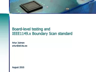
Motivation for Standard • Bed-of-nails printed circuit board tester gone • We put components on both sides of PCB & replaced DIPs with flat packs to reduce inductance • Nails would hit components • Reduced spacing between PCB wires • Nails would short the wires • PCB Tester must be replaced with built-in test delivery system -- JTAG does that • Need standard System Test Port and Bus • Integrate components from different vendors • Test bus identical for various components • One chip has test hardware for other chips
Purpose of Standard • Lets test instructions and test data be serially fed into a component-under-test (CUT) • Allows reading out of test results • Allows RUNBIST command as an instruction • Too many shifts to shift in external tests • JTAG can operate at chip, PCB, & system levels • Allows control of tri-state signals during testing • Lets other chips collect responses from CUT • Lets system interconnect be tested separately from components • Lets components be tested separately from wires
Tap Controller Signals • Test Access Port (TAP) includes these signals: • Test Clock Input(TCK) -- Clock for test logic • Can run at different rate from system clock • Test Mode Select(TMS) -- Switches system from functional to test mode • Test Data Input(TDI) -- Accepts serial test data and instructions -- used to shift in vectors or one of many test instructions • Test Data Output(TDO) -- Serially shifts out test results captured in boundary scan chain (or device ID or other internal registers) • Test Reset(TRST) -- Optional asynchronous TAP controller reset
SAMPLE / PRELOAD Instruction -- SAMPLE Purpose: Get snapshot of normal chip output signals Put data on bound. scan chain before next instr.
EXTEST Instruction • Purpose: Test off-chip circuits and board-level interconnections
INTEST Instruction • Purpose: • Shifts external test patterns onto component • External tester shifts component responses out
INTEST Instruction Clocks • Control of applied system clock during INTEST • Use of TCK for on-chip system logic clock
RUNBIST Instruction • Purpose: Allows you to issue BIST command to component through JTAG hardware • Optional instruction • Lets test logic control state of output pins • Can be determined by pin boundary scan cell • Can be forced into high impedance state • BIST result (success or failure) can be left in boundary scan cell or internal cell • Shift out through boundary scan chain • May leave chip pins in an indeterminate state (reset required before normal operation resumes)
CLAMP Instruction • Purpose: Forces component output signals to be driven by boundary-scan register • Bypasses the boundary scan chain by using the one-bit Bypass Register • Optional instruction • May have to add RESET hardware to control on-chip logic so that it does not get damaged (by shorting 0’s and 1’s onto an internal bus, etc.)
IDCODE Instruction • Purpose: Connects the component device identification register serially between TDI and TDO • In the Shift-DR TAP controller state • Allows board-level test controller or external tester to read out component ID • Required whenever a JEDEC identification register is included in the design
MSB LSB 31 28 Version (4 bits) 27 12 Part Number (16 bits) 11 1 Manufacturer Identity (11 bits) 0 ‘1’ (1 bit) Device ID Register --JEDEC Code
USERCODE Instruction • Purpose: Intended for user-programmable components (FPGA’s, EEPROMs, etc.) • Allows external tester to determine user programming of component • Selects the device identification register as serially connected between TDI and TDO • User-programmable ID code loaded into device identification register • On rising TCK edge • Switches component test hardware to its system function • Required when Device ID register included on user-programmable component
HIGHZ Instruction • Purpose: Puts all component output pin signals into high-impedance state • Control chip logic to avoid damage in this mode • May have to reset component after HIGHZ runs • Optional instruction
BYPASS Instruction • Purpose: Bypasses scan chain with 1-bit register
Instruction BYPASS CLAMP EXTEST HIGHZ IDCODE INTEST RUNBIST SAMPLE/PRELOAD USERCODE Status Mandatory Optional Mandatory Optional Optional Optional Optional Mandatory Optional Optional / Required Instructions