Download
1 / 17
170 likes | 462 Vues
Engineering Lecture1: Logic Circuits & Concepts about basic Electrical Engineering Devices. by Christin Sander. Logic Circuits Analogue vs Digital Binary Numbers Logic Gates Boolean Algebra Flip-Flops & Clocks Counters Data Storage. Electrical Engineering Overview of Transistors

E N D
Engineering Lecture1:Logic Circuits & Concepts about basic Electrical Engineering Devices by Christin Sander
Logic Circuits Analogue vs Digital Binary Numbers Logic Gates Boolean Algebra Flip-Flops & Clocks Counters Data Storage Electrical Engineering Overview of Transistors Amplifiers Operational Amplifiers Overview
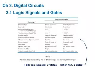
Analogue versus Digital Analogue: Digital: ANALOGUE signals vary in a continuous way, can take any values DIGITAL signals represent information as a sequence of discrete varying physical quantities, encode values into binary numbers (0 or 1)
Analogue to Digital Conversion • In nature, signals normally occur in an analogue way • To convert them into a digital signal, a threshold value is selected. • For values below the threshold: 0 • For values above the threshold: 1
Binary Number System The binary number system is the base 2 number system Uses 2 different symbols (0 and 1) A BInary digiT("BIT") in each position Binary logic circuits are useful for making controllers A binary system can also represent numbers of any magnitude Logic circuits can be realised which will perform arithmetical operations on these binary numbers This is the principle behind almost all digital calculators and computers Decimal Number System The decimal number system is the base 10 number system Uses 10 different symbols (0,1,2,…..9) In General, any number system can be used Binary Numbers
Logic Gates • Electronic circuits with one or more input wires and one output wire • The voltage on the output depends on the voltages on the inputs • The relationship between inputs and output is a logical function, determined by the circuit arrangement inside the gate. Circuit (made up of transistors used as switches)
Flip-flops • Divide-by-2-circuit • D Flip-flop • Ripple-Down Counter
J-K Flip-flop • Q+ indicates the value of Q after the next clock pulse • If J and K are different, Q takes on the value of J • If J and K are both 0, Q remains unchanged • If J and K are both 1, Q changes to its inverse (it "toggles") • Information from J and K is read in on the rising edge of the clock, and is translated into action at the Q outputs on the FALLING edge of the clock
Synchronous Counter • Synchronous Counter (8-bits)
Data Register • A circuit which can store temporarily all bits of a binary number A 3-bit register (a typical personal computer will have several 16-bit and 32-bit data registers in its arithmetic unit)
Storage Devices: ROM • A ROM cell • Typical m-ROM device
Transistors • Small input current controls a large output current • Can act as a switch if in saturation or cut-off region
Amplifiers • An amplifier is a device that accepts a small signal and outputs a larger signal that generally matches the waveform characteristics of the input It amplifies the input signal • Factors affecting amplification • Gain: Relationship of input and output signal • Efficiency • Bandwidth • Settling time • Noise
Operational Amplifiers • An opamp is a device that takes an analogue signal and amplifies it • Output voltage depends on difference of input voltage • Applications: • Analogue to digital converters • Filters • Comparators