Download
1 / 28
280 likes | 434 Vues
low loss superconducting Rutherford Cable for DiscoRap. v. 1. Overview. 1 introduction & first trials superconductor design specifications & manufacture status qualification. 1 introduction & first trials superconductor design specifications & manufacture status qualification.

E N D
Overview • 1 introduction & first trials • superconductor design • specifications & manufacture status • qualification
1 introduction & first trials • superconductor design • specifications & manufacture status • qualification
Our work started from the first developments, performed in 2002-2004 by GSI, for the Rutherford cable design for the SIS-300 dipoles. The Rutherford cable layout, its dimensions and the number of strands, were taken from the LHC dipole outer cable, with the insertion of a stainless steel core to increase Rc. This decision was taken immediately after the change from the SIS 200 to SIS 300 synchrotron design; GSI 001 (SIS200) Rutherford cable design was based on RHIC dipole, with 30 x 0.648 mm strands. To reach a 1 K temperature margin it would have been necessary to have more than 48 0.648 mm strands. Therefore the dimensions of the existing LHC dipole outer layer conductor were chosen. The preliminary magnetic analyses of the 4.5 T, single layer, INFN design have shown that an analogous margin could be achieved by using the same Rutherford cable, which was therefore adopted. “historical” background
Frascati ECOMAG meeting From M. N. Wilson GSIReport no. 29: ...At the Oct 2005 ECOMAG meeting in Frascati, (...) we came to some important conclusions about this wire: a) Single stacking produces the lowest filament distortion but stacking the enormous numbers of rods required (23 000 for 3.5 mm filaments and 45 000 for 2.5 mm) is not a practical process. So we probably have to accept the distortion of a double stack process and make the filaments proportionately finer. b) Cu-0.5%Mn is good for suppressing proximity coupling and has a resistivity which is much higher than pure Cu, but not too high (in my view Cu-15%Ni has a too high resistance – and too low thermal conductivity). c) Cu-0.5%Mn is much better matched to Cu in deformation characteristics than is Cu-15%Ni. d) Only the minimum amount of CuMn needed to minimize coupling should be used in the wire, elsewhere pure Cu should be used because it improves stability and quench protection.
Prototype wire NbTi/CuMn Cu The “prototype wire” is based on cold drawing of seven elements of Luvata OK3900 wire already in stock. Although significantly different from the final wire, it has allowed to show that reasonably high Jc and short twist pitch lengths can be realistically achieved on wires with NbTi fine filaments embedded in a CuMn matrix, with a diameter around 2 - 3 μm (see next slide). Geometrical filament diameter 2.52 μm Small apparent deformation
Jc and n-index as a function of the twist pitch Heat treatments were not optimized for the final filament diameter, further improvment may be expected Jc @ 5 T, 4.2 K 2,500 A/mm²
1 introduction & first trials • superconductor design • specifications & manufacture status • qualification
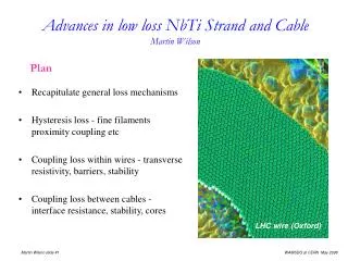
Eddy currents (z) Laplace Equation Boundary condition around the filamentary areas y z E.C. term Interfil. term x “effective” transverse resistivity Interfilamentary coupling Therefore we use the term transverse resistivity in a wider meaning; it describes both the transverse current and the EC losses. The EC’s contribute to 10-15% of the total losses Filament Coupling LossesProblem statement dB/dt
Solving the problem:analytical approach Duchateau, J.L. Turck, B. & Ciazynski, D. have developed a model, based on a simplified geometry, with cylindrical symmetry. In this model, the above-seen equations may be solved analytically. We have improved their approach, to better suit our geometry, increasing the number of annular regions. The Laplace equation has then been solved. Outer Cu Sheath (CuMn Barrier) Filamentary area Cu area Cu core (CuMn Barrier) Filamentary area Duchateau, J.L. Turck, B. Ciazynski, D. “Coupling current losses in composites and cables: analytical calculations” Ch. B4.3 in “Handbook of Applied Superconductivity”, IoP 1998
Solving the problem:FEM solution • Given the geometry and the BC’s, the Laplace solution can be solved with FEM as well. • Here we show the potential φ (colour map), and the in-plane x-y (i.e. related to the interfilament coupling) current density. • The total power dissipation Q is again found by numerical integration of E², and adding the EC term. From Q we compute the effective transverse resistivity.
Transverse resistivity from Analytical & FEM methods □ 1st generation ◊ 2nd generation Green good coupling Red poor coupling Full FEM Empty analytical Black line: specification value Good agreement, 15% or better, between FEM and analytical computations
equivalent diameter << Dynamic stability The stability criterion appears to be satisfied: Thermal conductivity Weighed average beteween NbTi and CuMn 1.87 W/mK Approach “à la Carr” 1.14 W/mK l (NbTi fill factor in the bundle) 0.526 Jc @ 4.2 K, 5 T 2700 A/mm2 rCu @ 4.2 K, 5 T 3.5 · 10-10 ohm·m Characteristic length 22 mm Round filament factor form 4√2 “ 120 mm Equivalent macrofilament diameter Inner, Outer 25 mm So the margin for stability seems comparable or better to the layouts envisaged by MNW in Rep 29. 0.1 W/mK 4.4 W/mK
1 introduction & first trials • superconductor design • specifications & manufacture status • qualification
SC Rutherford Cable for Magnet Winding:The Contract A first contract for superconducting Rutherford cable for magnet winding has been awarded to Luvata Superconductors, through its Fornaci di Barga (Italy) Businness Unit. The following material will be supplied: 1080 m (3 unit lenghts) of 1st generation Cable. Two units will be used for winding each of the two poles composing the 4 m long prototype magnet, while the third will serve as a spare. 720 m (2 unit lenghts) of 2nd generation Cable. These units will be used to wind future model magnets. The same basic geometry will be used for both the first and the second generation, with a filament geometrical diameter 2.65 μm. The two designs will involve different lay outs to achieve different values of ρt. Delivery of 1st generation is expected in June 2009
SC Rutherford Cable for Magnet Winding:Wire Design The same basic geometry will be used for both the first and the second generation. Design filament geometrical diameter 2.65 μm. The design involves sub-elements with Cu outer sheath and sub-elements with CuMn outer sheath. Both have CuMn interfilamentary matrix. The number of Cu-sheath and CuMn-sheath elements differ between 1 st and 2 nd generation, to achieve different values of ρt. Wire Component Volume Fractions. Min. Jc @ 5 T , 4.2 K before cabling 2,600 A/mm² Target Jc “ “ 2,700 A/mm² Expected cabling degradation ≤ 5%
SC Rutherford Cable for Magnet Winding:Wire Transverse Resistivity
Contract for a second wire development INFN believes that it is important to qualify a second supplier, also in order to test different technical solutions An order has been awarded to Bruker EAS for the manufacture of: 80 km of SC wire, small filament, CuMn barriers It must be emphasized that only wire double stack extrusion only one design 64,000 filament (wrt 38,000 in Luvata order), 2 mm filaments geometrical (wrt 2.65 mm in Luvata order) Delivery: 12 months (March 2010)
1introduction & first trials • superconductor design • specifications & manufacture status • qualification
Magnetization, CuMn contribution Δm 10 K 4.2 K The CuMn paramagnetism has an effect on the harmonic content of the field within the magnet bore. In our case, the largest effect is < 10-4 for sextupole.
Magnetization, effective diameter @ 5T Ic = 295 A Δm = 2.2·10-12 Wb·m Lsample = 4.7 mm deff = 3.0 μm dgeo = 2.5 μm
3 19 35 36 Ra & Rc measurement Rc >> Ra • Voltage was measured with: • a Agilent scanner with a µV sensitivity on 20 channels. • a high-resolution HP34420 nanovoltmeter + 8 channel scanner (red numbers in the upper sketch). NOTE: in our mea’s voltages are w.r.t. current output (wire#19), here are w.r.t. wire #1
Ra & Rc measurement In order to test the measuring apparatus, we have measured Ra on the “superdummy” Rutherford cable used for winding the test poles; The sample was “as provided”, i.e. no curing was done; The force applied on the sample cooled at 4.2 K was controlled precisely by an mechanical test machine; The force was changed during the same thermal cycle;
first results: voltage drop Ra 325 µΩ Rc is assumed to >> Ra
from voltage drop to Ra Ra 325 µΩ
conclusions -the Rutherford cable manufacture at Luvata is running smoothly; -a second contract for the SC wire has been awarded to Bruker EAS; -soon we shall know the performances of these demanding Rutherford Cables 28