Download
1 / 18
600 likes | 2.24k Vues
Thrust bearings. Support the axial thrust of both horizontal as well as vertical shafts Functions are to prevent the shaft from drifting in the axial direction and to transfer thrust loads applied on the shaft

E N D
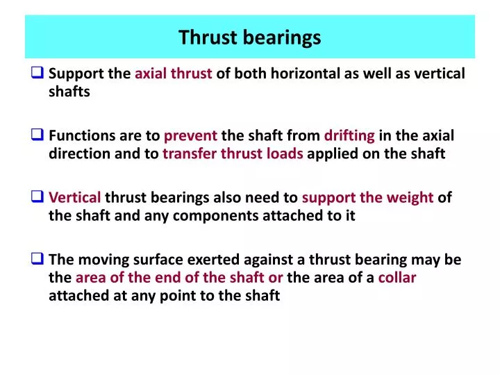
Thrust bearings • Support the axial thrust of both horizontal as well as vertical shafts • Functions are to prevent the shaft from drifting in the axial direction and to transfer thrust loads applied on the shaft • Vertical thrust bearings also need to support the weight of the shaft and any components attached to it • The moving surface exerted against a thrust bearing may be the area of the end of the shaftor the area of a collar attached at any point to the shaft
Types of thrust bearings Plain thrust: Consists of a stationary flat bearing surface against which the flat end of a rotating shaft is permitted to bear Flat end of rotor ROTOR Axial movement Bearing surface
Thrust bearing- flat land type • They handle light loads for simple positioning of rotors • They are usually used in conjunction with other types of thrust bearings • They carry 10 to 20% of the overall axial load • Bearing surface sometimes incorporated with oil grooves that help store and distribute oil over the surface ROTOR Oil grooves for storing and distributing oil over the surface
Thrust bearing- step type • Step bearing: Consists of a raised or stepped bearing surface upon which the lower end of a vertical shaft or spindle rotates • The entire assembly is submerged in lubricant • Stepped bearings are either designed to undergo hydrodynamic lubrication or are lubricated hydrostatically (external pump) ROTOR Wedge formation or pressurized oil supply Bearing
Thrust bearing- hydrostatic type • These depend on an external pump to provide oil under pressure to form a load-bearing film between surfaces • Used in equipment with extremely low speeds as a hydrodynamic film cannot form ROTOR Bearing surface Oil under pressure, supplied by pump
Thrust bearing- collar type Oil supply Bearing surface Collar type Shaft rotates Shaft Loads are borne by the bearing surface that comes in contact with the collar which is attached to the shaft Collar Shaft moves in axial direction too
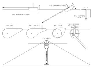
Thrust bearing- tilting pad type (Michell type) • The surfaces are at an angle to each other • One surface is usually stationarywhile the other moves • Undergoes hydrodynamic lubrication, therefore formation of a wedge of lubricant under pressure • The amount of pressure build up depends on the speed of motion and viscosity • The pressure takes on axial loads
Thrust bearing- Tilting pad type Propeller Pushes ship forward Collar Direction of rotation Bearing plate Pivot Tilting pad rotates around the pivot (angle of tilt varies) Oil wedge Shaft • Back thrust from water to propeller causes axial loading on the shaft • Axial loads are opposed by pressure buildup in the wedge • Gives a damping effect • Passes on thrust to the ship Axial loads from machinery being driven In this case thrust from propeller
Tilting thrust bearings- basic geometry h1 = distance of separation at leading edge h2 = distance of separation at trailing edge U = velocity of lower pad in the x – direction B = bearing breadth The film thickness “h” at any point is given by: Leading edge Z x h1 h h2 Trailing edge B U X
Height ratios , therefore Let or The expression for pressure gradient was derived earlier as Z Where p is the pressure h is the coefficient of dynamic viscosity ho is the separation distance at max. pressure U is the velocity of the bottom surface Top surface is stationary h1 h h2 U X
Making the equation non-dimensional Let A = ho/h2 such that ho = Ah2 Substituting this and the value of h in terms of x we get On rearranging we get: Let x* = x/B, a dimensionless length, so that
Pressure distribution equation Now h22/UhB has the dimensions of (pressure)-1 so it is possible to write (h22/6UhB)p as p*, the non-dimensional pressure. The equation therefore becomes This is Reynold’s equation in non-dimensional form applied to inclined pads. Integration gives the pressure distribution. On integration we get:
Applying boundary conditions A and C are constants of integration. In order to evaluate them the value of pressure is required at two specific positions. This, in the case of a pad, is taken as the ambient pressure at the leading and trailing edges, where the pressure curve starts and stops. These pressures are usually considered as zero. Therefore the conditions are: p = 0 at x = 0, and x = B Non-dimensionalizing we get, p* = 0 at x* = 0 and x* = 1 (since x* = x/B) First putting p* = 0 at x* = 0, we get:
Obtaining the constants of integration Then putting p* = 0 at x* = 1, we get: The above two equations can be solved to give: and Thus: Which can be simplified to give:
Maximum pressure The max. dimensionless pressure po* occurs when dp/dx = 0, h = ho, and x = xo. Now, and Therefore
Load carried Integration of the pressure across the bearing gives the load carried per unit length, W/L So which can be defined as the non- dimensional load W*. Thus Which reduces to (as x* = x/B)
Tilting pad bearing- expression for load Now Therefore This equation was first derived by Reynold’s for a fixed inclined surface
Height variation with pivot point The ratio h1/h2 = (1+K) is determined by the position of the pivot point Upper pad rotates around the pivot point Pivot point Z • The position of the pivot point is found by taking moments about the leading edge. • For stability it should be at the center of pressure h1 x h h2 Velocity U X