Download
1 / 19
200 likes | 442 Vues
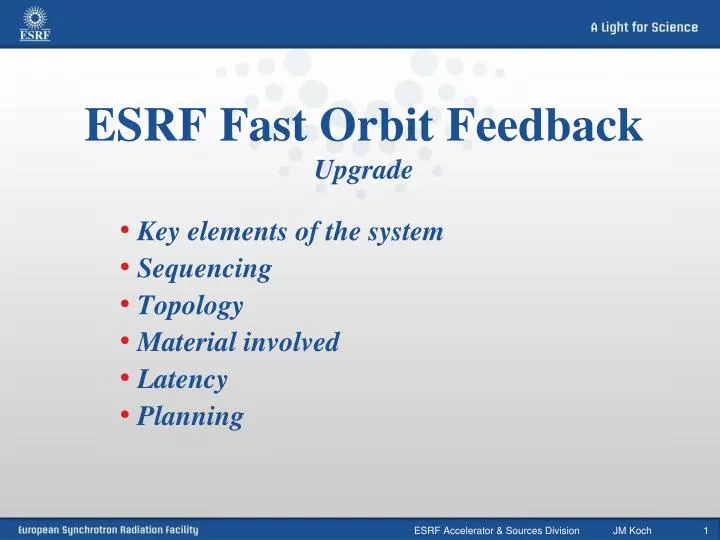
ESRF Fast Orbit Feedback Upgrade. Key elements of the system Sequencing Topology Material involved Latency Planning. ESRF Fast Orbit Feedback. Fast Orbit Feedback improvement. Key elements of the system. 224 Libera BPMs. One unique system to cover the full frequency range.

E N D
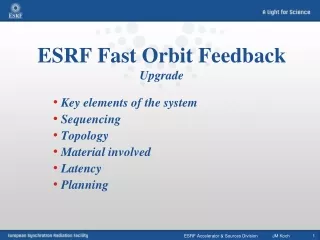
ESRF Fast Orbit FeedbackUpgrade • Key elements of the system • Sequencing • Topology • Material involved • Latency • Planning ESRF Accelerator & Sources Division JM Koch
ESRF Fast Orbit Feedback Fast Orbit Feedback improvement Key elements of the system 224 Libera BPMs One unique system to cover the full frequency range 96 Horizontal & Vertical steerers housed in the sextupoles ESRF Accelerator & Sources Division JM Koch
One of the 8 Feedback Processors ESRF Fast Orbit Feedback Fast Orbit Feedback sequencing 1: Beam position acquisition on 224 Libera BPMs ----- ----- 7 Liberas In each of the 32 cells Ethernet Group of 7 Liberas per cell 4 cabinets of 18 corrector’s channels each One of the 96 sextupoles housing the correctors One of the 224 Beam Position Monitors ESRF Accelerator & Sources Division JM Koch
One of the 8 Feedback Processors ESRF Fast Orbit Feedback Fast Orbit Feedback sequencing 2: All positions exchanged between Liberas… …and transferred to signal processors ----- ----- Ethernet Group of 7 Libera BPMs per cell 4 cabinets of 18 corrector’s channels each One of the 96 sextupoles housing the correctors One of the 224 Beam Position Monitors ESRF Accelerator & Sources Division JM Koch
One of the 8 Feedback Processors ESRF Fast Orbit Feedback Fast Orbit Feedback sequencing 3: Corrections computation on 8 stations (FPGAs) ----- ----- Ethernet Group of 7 Libera BPMs per cell 4 cabinets of 18 corrector’s channels each One of the 96 sextupoles housing the correctors One of the 224 Beam Position Monitors ESRF Accelerator & Sources Division JM Koch
One of the 8 Feedback Processors ESRF Fast Orbit Feedback Fast Orbit Feedback sequencing 4: Corrections transferred to Power Converters ----- ----- Ethernet Group of 7 Libera BPMs per cell 4 cabinets of 18 corrector’s channels each One of the 96 sextupoles housing the correctors One of the 224 Beam Position Monitors ESRF Accelerator & Sources Division JM Koch
One of the 8 Feedback Processors ESRF Fast Orbit Feedback Fast Orbit Feedback sequencing 5: Current sent to the correctors… … and corrections applied to the beam ----- ----- Ethernet Group of 7 Libera BPMs per cell 4 cabinets of 18 corrector’s channels each One of the 96 sextupoles housing the correctors One of the 224 Beam Position Monitors ESRF Accelerator & Sources Division JM Koch
One of the 8 Feedback Processors ESRF Fast Orbit Feedback Fast Orbit Feedback sequencing 5: Current sent to the correctors… … and corrections applied to the beam ----- ----- Ethernet Group of 7 Libera BPMs per cell 4 cabinets of 18 corrector’s channels each One of the 96 sextupoles housing the correctors One of the 224 Beam Position Monitors ESRF Accelerator & Sources Division JM Koch
ESRF Fast Orbit Feedback Data from digital B.P.M.s Topology(1/4 of the machine) 6 H&V 18 ch 8 H&V 24 ch 6 H&V 18 ch 7 H&V 21 ch Correctors Power Supplies Correctors Power Supplies Correctors Power Supplies Correctors Power Supplies E t h 18 RS485 24 RS485 18 RS485 21 RS485 C P U PMC Feedback Processor DSP-1 PMC Feedback Processor DSP-1 PMC Feedback Processor DSP-2 PMC Feedback Processor DSP-2 Rocket IO Rocket IO --- BPM BPM BPM BPM BPM BPM BPM BPM Cell+n Cell+m Cell-n Cell-m BPMs of 1 cell over 8 and correctors scheme for 1/4th of the machine (SRDC location example) ESRF Accelerator & Sources Division JM Koch
ESRF Fast Orbit Feedback Material involved Digital B.P.M. Libera Brilliance Acquisition: • 224 H & V positions from Libera BPMs grouped by cells (7/cell) Position data rate for fast orbit feedback: 10kHz There are 2 kinds of communication channels: Fast Communication for data exchange at 10kHz RocketIOs Configuration, slow rate monitoring Ethernet Libera Brilliance. Set-up for one cell Fast communication: copper for the very short links inside one rack and optic fiber for the inter-cells connections ESRF Accelerator & Sources Division JM Koch
ESRF Fast Orbit Feedback Topology 10kHz communication network Communication Controller fromDiamond Light Source: “Every 100µs, each BPM injects its own beam position values to the FOFB network, and then starts a forwarding or discarding process on the BPM values that it receives. Each BPM position then propagates to all 224 BPMs and the 8 processing modules on the network before the end of the time frame.“ Libera Brilliance and Digital Signal Processors communication network is redundant The full exchange of 224 positions H & V will take 50µs even if a connection is broken ESRF Accelerator & Sources Division JM Koch
ESRF Fast Orbit Feedback Topology (1/4 of the machine) Digital Signal Processing 6 H&V 18 ch 8 H&V 24 ch 6 H&V 18 ch 7 H&V 21 ch Correctors Power Supplies Correctors Power Supplies Correctors Power Supplies Correctors Power Supplies E t h 18 RS485 24 RS485 18 RS485 21 RS485 C P U PMC Feedback Processor DSP-1 PMC Feedback Processor DSP-1 PMC Feedback Processor DSP-2 PMC Feedback Processor DSP-2 Rocket IO Rocket IO --- BPM BPM BPM BPM BPM BPM BPM BPM Cell+n Cell+m Cell-n Cell-m BPMs of 1 cell over 8 and correctors scheme for 1/4th of the machine (SRDC location example) ESRF Accelerator & Sources Division JM Koch
ESRF Fast Orbit Feedback Material involved Commercial card in a PCI, same behaviour than Libera (Embedded Diamond L.S. Communication Controller): PMC module (Gbit Ethernet + Virtex-II FPGA) • As communication node and signal processor, the FPGA will embed the signal processing • Real time inside the FPGA • For diagnostic purposes or transfer of parametersthrough the PCI interface • Not real time ESRF Accelerator & Sources Division JM Koch
ESRF Fast Orbit Feedback Material involved • Digital Signal Processing: • Multiplication by the inverted response matrix, • Digital P.I. correction, • RS485 Power Converters command. • On an FPGA the computation can be split on many channels running in parallel, the time for computation can be estimated for one channel only: • One compromise between FPGA area occupation and speed can lead to : • 224 multiplications + sum, this gives a total of about 300 cycles of the FPGA less than 3µs PMC module (Gbit Ethernet + Virtex-II FPGA) ESRF Accelerator & Sources Division JM Koch
AC/DC PS units AC/DC PS units AC/DC PS units AC/DC PS units ESRF Fast Orbit Feedback Steerers Power Supplies Topology (1/4 of the machine) 6 H&V 18 ch 8 H&V 24 ch 6 H&V 18 ch 7 H&V 21 ch Correctors DC Power Supplies Correctors DC Power Supplies Correctors DC Power Supplies Correctors DC Power Supplies E t h 18 RS485 24 RS485 18 RS485 21 RS485 C P U PMC Feedback Processor DSP-1 PMC Feedback Processor DSP-2 Rocket IO Rocket IO --- BPM BPM BPM BPM BPM BPM BPM BPM Cell+n Cell+m Cell-n Cell-m BPMs of 1 cell over 8 and correctors scheme for 1/4th of the machine (SRDC location example) ESRF Accelerator & Sources Division JM Koch
ESRF Fast Orbit Feedback Material involved Correction: • Steerers: 96 Horizontal & Vertical • Power supplies: 3*96 channels able to drive up to +/- 2 Amp DC and small currents up to 200Hz (+/- 17 bits resolution) 288 channels located in 18 cubicles grouped by ¼ of the machine in the technical gallery. ¼ of the steerers DC Power Converters to be replaced by AC-DC Power Converters The corrections will be applied at the acquisition rate, each 100µs. A prototype of AC power supply has been validated in real situation. The correctors are part of the sextupoles (6 black coils) ESRF Accelerator & Sources Division JM Koch
Critical inside the 100 µs time frame Libera ESRF Fast Orbit Feedback ESRF Fast Orbit Feedback latency Group delay of FIR: 148 µs Group delay of 2 IIR: <71 µs Distribution of data around the ring (DLS C.C.): 50 µs * Signal processing: 10 µs ** Write into PS controller: 20 µs Power supply: 70 µs Eddy currents in the sextupoles: 75 µs Eddy currents in vacuum chamber (stainless-steel): 265 µs .. Total: <709 µs * Data from Diamond Light Source ** Inside the 8 dedicated FPGAs ESRF Accelerator & Sources Division JM Koch
ESRF Fast Orbit Feedback ESRF Fast Orbit Feedback implementation planning • Optic fibers for the dedicated network March 2009 • Communication Controller on Liberas and one PMC-FPGA processor Spring 2009 • AC Power Converter prototype validation Spring 2009 • Server for multi-turns diagnostics Summer 2009 • AC Power Converters installed for DC corrections only (Remote access through Ethernet) fast correction based on air coil correctors remains active 2010 • Implementation of the fast orbit correction on 8 PMC-FPGA processors End 2010 ESRF Accelerator & Sources Division JM Koch
ESRF Fast Orbit Feedback Acknowledgements Nicolas Hubert (Soleil) Nicolas Leclerc (Soleil) Michael Abbott (Diamond Light Source) Tony Dobbing (Diamond Light Source) Gunther Rheim (Diamond Light Source) Isa Uzun (Diamond Light Source) Francis Epaud (ESRF) Eric Plouviez (ESRF) ESRF Computing service ESRF Diagnostic group ESRF Power Supply group Thank you for your attention ! ESRF Accelerator & Sources Division JM Koch