Download
1 / 23
230 likes | 234 Vues
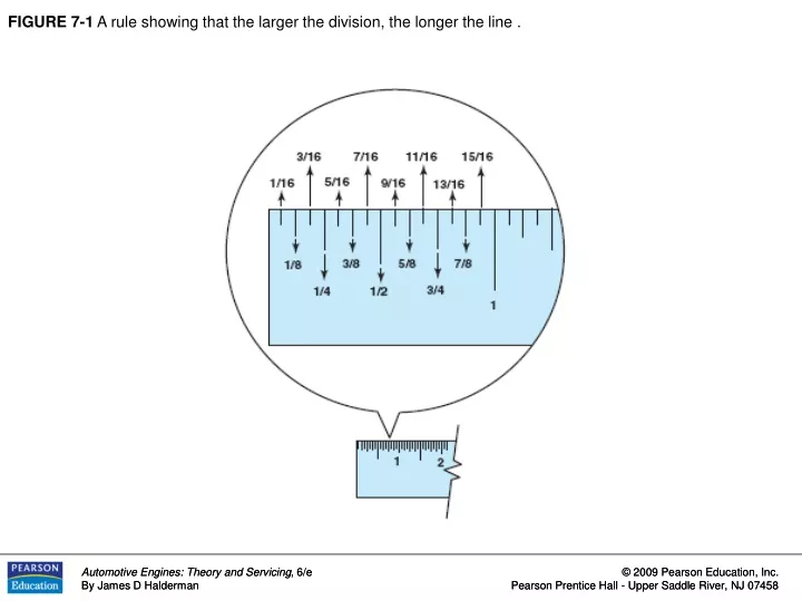
FIGURE 7-1 A rule showing that the larger the division, the longer the line. FIGURE 7-2 A plastic rule that has both inches and centimeters. Each line between the numbers on the centimeters represents one millimeter because there are 10 millimeters in 1 centimeter.

E N D
FIGURE 7-1 A rule showing that the larger the division, the longer the line .
FIGURE 7-2 A plastic rule that has both inches and centimeters. Each line between the numbers on the centimeters represents one millimeter because there are 10 millimeters in 1 centimeter.
FIGURE 7-3 A typical micrometer showing the names of the parts .
FIGURE 7-4 All micrometers should be checked and calibrated as needed using a gauge rod.
FIGURE 7-5 The three micrometer readings are (a) 0.0212 inch; (b) 0.0775 inch; (c) 0.5280 inch. These measurements used the vernier scale on the sleeve to arrive at the ten-thousandth measurement. The number that is aligned represents the digit in the ten-thousandth place.
FIGURE 7-6 Metric micrometer readings that use the vernier scale on the sleeve to read to the nearest 0.001 millimeter.
FIGURE 7-7 Using a micrometer to measure the connecting rod journal for out-of-round and taper.
FIGURE 7-8 Crankshaft journal measurements. Each journal should be measured in at least six locations, but also in position A and position B and at 120-degree intervals around the journal.
FIGURE 7-9 Camshaft journals should be measured in three locations, 120 degrees apart, to check for out-of-round.
FIGURE 7-10 Checking a camshaft for wear by measuring the lobe height with a micrometer.
FIGURE 7-11a When the head is first removed, the cylinder taper and out-of-round should be checked below the ridge.
FIGURE 7-11b When the head is first removed, the cylinder taper and out-of-round should be checked above the piston when it is at the bottom of the stroke.
FIGURE 7-12a A telescopic gauge being used to measure the inside diameter (ID) of a camshaft bearing.
FIGURE 7-12b An outside micrometer used to measure the telescopic gauge.
FIGURE 7-13 Cutaway of a valve guide with a hole gauge adjusted to the hole diameter.
FIGURE 7-14 The outside of a hole gauge being measured with a micrometer.
FIGURE 7-15 (a) A typical vernier dial caliper. This is a very useful measuring tool for automotive engine work because it is capable of measuring inside and outside measurements. (b) To read a vernier dial caliper, simply add the reading on the blade to the reading on the dial.
FIGURE 7-16 A group of feeler gauges (also known as thickness gauges), used to measure between two parts. The long gauges on the bottom are used to measure the piston-to-cylinder wall clearance.
FIGURE 7-17 A feeler gauge, also called a thickness gauge is used to measure the small clearances such as the end gap of a piston ring.
FIGURE 7-18 A straightedge is used with a feeler gauge to determine if a cylinder head is warped or twisted.
FIGURE 7-19 A dial indicator is used to measure valve lift during flow testing of a high performance cylinder head.
FIGURE 7-20 A dial bore gauge is used to measure cylinders and other engine parts for out-of-round and taper conditions.
FIGURE 7-21 A depth micrometer being used to measure the height of the rotor of an oil pump from the surface of the housing.