Download
1 / 27
270 likes | 431 Vues
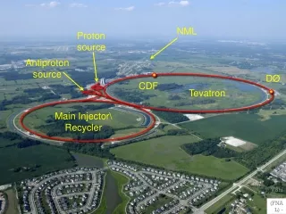
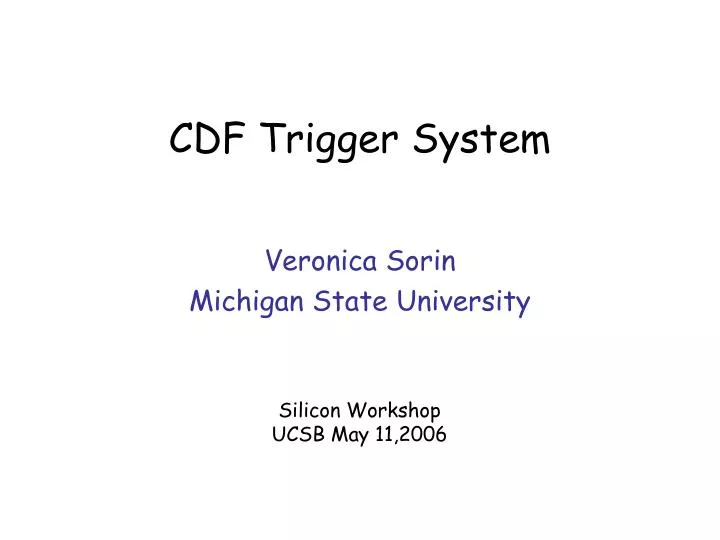
CDF Trigger System. Veronica Sorin Michigan State University. Silicon Workshop UCSB May 11,2006. Why is trigger so important?. Tevatron provides collisions at a rate of ~1.7MHz Event size ~ 200kB actual CDF output to tape 20MB/s Trigger rejects 99.995% of crossings !.

E N D
CDF Trigger System Veronica Sorin Michigan State University Silicon Workshop UCSB May 11,2006
Why is trigger so important? • Tevatron provides collisions at a rate of ~1.7MHz • Event size ~ 200kB • actual CDF output to tape 20MB/s Trigger rejects 99.995% of crossings ! • Select events of interest, but : • Inel ~ 50mb • For example top ~ 7pb • That is a ~1/1010 factor !!! Need a trigger system that, keeps with high efficiency events of interest while rejecting unwanted ones
170 100 50 2002 2003 2004 2005 Peak luminosity (1030 cm-2 s-1 ) Multiple interactions 36 x 36 bunches 396ns between bunch crossings 1.7MHz crossing rate At High Luminosity: Multiple interactions ! High detector occupancy Instantaneous Luminosity (run 211554)
constant rate constant s “growth terms” Trigger Cross Sections • For any process: rate R = L(L = instantaneous luminosity, = cross section.) • For a physics process, is independent of L. • For trigger cross sections, we observe: s = A/L + B + CL + DL2 • A, B, C, D are constants depending upon trigger. • High purity triggers typically have C~D~0. • Two effects cause extra powers of L: • Overlapping objects from different interactions. • Fakes that are luminosity dependent. • Rates: R=L = A + BL + CL2 + DL3
Efficiency and Dead-time • Goal of trigger is to maximize collection of data for physics process of interest: • Aim for high efficiency ! • For each process, look for: • And watch the dead-time ! • Trigger Dead-time: • Due to fluctuations, incoming rate is higher than processing onevalid interactions are rejected due to system busy • Buffering incoming data could reduce dead-time • But dead-time always incurred if • <incoming rate> > 1/<processing time> ! etrigger = Ngood(accepted)/Ngood(Produced)
CDF Trigger Implementation • To obtain high efficiency while large background rejection: • Multiple Trigger Levels • Reject in steps with successively more complete information • In each step, reject a sufficient fraction of events to not incurred in high dead-time at next stage • Basic Idea: L1 – fast (~few ms) with limited information, hardware based L2 – moderately fast (~10s of ms), hardware/software L3 – Commercial processor(s)
CDF has implemented a 3 level trigger • Level-1 is a synchronous hardware trigger • - Processing in parallel pipelined operation • - L1 decision always occurs at a fixed • time (~5s after beam collision) • - Input rate = 1.7MHz • L1A rate ~ up to 35KHz • Level-2 is a combination of hardware and • software trigger (asynchronous) • - Average Level-2 processing time is ~30s • - L2A rate ~ up to 600Hz • Level-3 is purely a software trigger • - Massive PC farm running offline-type code • - Reconstruct complete events • - L3A rate ~ 100Hz • Total Data rejection factor 1 : 20000 SVX reads out to VRBs after L1A (not L2A)
What do we trigger on? • Various trigger subsystem generates • primitives that we can “cut” on • Available trigger primitives are: • At L1: • - Central tracking (XFT pT>1.5GeV), • - Calorimeter (EM and HAD) : • Electron (Cal +XFT), • Photon (Cal), • Jet (EM+HAD) • - Missing Et, SumEt, • - Muon (Muon + XFT) • At L2: • - L1 information • - SVT (displaced track, d0) • - Jet cluster • - Isolated cluster • - Calorimeter ShowerMax L1 can output 64 different triggers
What is a Trigger Table? • Trigger table is how our “trigger menu” is called: • “list” of selection criteria • Each item on the menu: • Is called Trigger Path • has three courses: L1, L2 and L3 “recipes”: • Set of cuts-parameter/instructions particular of each level. • An event is stored if one or more trigger path criteria are met. • Each time data taking starts (“a run”), the whole content is communicate to the system • For bookkeeping, all “menus” and “recipes” are store in a specially designed Database .
Dynamic prescale For large rate backup triggers, a prescale can be applied • Prescale (PS) means to only accept a predetermined fraction of events • The fraction is a fixed value for all luminosities (parameter stored in table for each particular trigger) • Value determined accordingly to needed statistics (and system availability) Trigger cross sections grow with luminosity as luminosity falls during a run trigger resources are freed up. • What if we could change the prescale value while data taking?
L2Accept Rate (Hz) DPS Prescale change • Dynamic prescales up and running since late 2002 • Applied to triggers with high growth term • Dynamic prescale (DPS) is a feedback system • Reduces the prescales as luminosity falls • Changes happen based on rates information accumulated on a time scale of minutes and amount of change depends on available trigger bandwidth at a given time
UPS kicks in L1Accept Rate (Hz) Lumi (E30) The feedback can be also done at the sec scale ! This is what we call the “Uber Prescale (UPS)”, it is still DPS. • Enabling high rate L1 triggers • whenever the system is idling. • (effectively look at buffer occupancy) • In trigger table since 2004 • Applied to high rate L1 track trigger • One simple approach: • Luminosity enable (DPS based on just luminosity): • Turns on/off a particular trigger at a given Instantaneous Luminosity. In table since 2005.
Hardware improvements • Hardware improvements are a key to maintain system alive, especially at high luminosities • Example: reduction in Level 2 execution time improves the bandwidth for L1A • Examples are: • L2 Pulsar upgrade for L2 decision crate • New system based on : • Universal interface board design PULSAR • Commodity processor (LINUX PC) • Fully operational since early 2005 • L2 SVT upgrade • Improve pattern recognition • Increase processing time speed • Fully operational since early 2006 Average gain ~20 sec Before: 5% deadtime with L1A 18KHz @ ~< 50E30 After: 5% deadtime with L1A 25KHz @ ~ 90E30
(nb) L2 CMX Muon + track Lum (1030) L2 Jet40 Lum (1030) High Luminosity effects Cross section grows with luminosity: s = A/L + B + CL + DL2 Two examples: • Fake tracks: Track trigger rates growing rapidly with luminosity Dominant component comes from fake tracks • Jet Triggers: Current L2 Clustering algorithm sensitive to detector occupancy, “temporary” solution: increase tower threshold on very forward region
Tevatron performance Average Peak Luminosity Projections (design) Peak Luminosity (E30) Exciting and challenging times to come !!!! Peak luminosity record: 1.8 1032 cm-2 s-1 Integrated luminosity • weekly record:27 pb-1 /week • total delivered:1.5 fb-1
How CDF was doing…? Time ago…. Because of high deadtime, at luminosity above 90E30, we had to run with a special trigger table with a smaller set of triggers: the so called “high lumi table” ... Time ago… Data taken Jun-Jul 2004
How are we doing now (2006) ? • Significant trigger table performance optimization/improvements in the past year • Take advantage of: L2/SVT/EVB/L3 upgrade improvements • Only one table running during whole store 2006 * L3 means Trigger paths <Dead-time> ~5% Collaboration Effort !
Run 211554-data taken Feb 12 2006 L1 Accept Rate (Hz) L3A Rate (Hz) UPS Lumin Enable 1.3fb-1 data on tape to analyze ! L2A Dead-time (%) 600 DPS 300 5 Lum (E30) Lum (E30)
How we got here…. • Each Trigger table change: • cycle includes testing at Control Room • Keep Silicon safe • No beam test (no colliding beam) • Beam test (end-of-store -> low luminosity): • NO SILICON : check performance, watch L1A rate • With SILICON test: monitor rates Si rep required in CR for this tests • Big accomplishment last year hard work from many people new default Many thanks to Si group !
Summary • Trigger is very important and interesting at hadron colliders • Trigger is also very challenging, make it even more interesting • One of the best places for young physicists to get trained on large experiment Be a trigger person, Join the fun !!!
Level 2 Decision Crate Upgrade • The L2 Decision Crate is the heart of L2 • Receives data from 7 preprocessors ( L1 Trigger, Calorimeter, Calorimeter isolation, ShowerMax (electrons), Muon, L1 Track (XFT) and L2 Silicon Tracking ) • Processor runs L2 algorithm and makes L2 Trigger decision Upgraded from • 6 flavors of custom interface boards • Custom Alpha processor • Data to processor on Custom Bus • Pulsar board as universal interface • Use CERN S-LINK technology • Linux PC • Easily to upgrade when faster processor becomes available to
Full upgrade in place since September 2005. • Has already shown high reliability • Flexibility allows for future improvements to cope with increase of luminosity • Average gain ~20 sec
Before SVT/L2 Upgrade Lumi 20-50E30 Dead time % Summer 2005 Lumi 90E30 Lumi 45E30 18KHz 25KHz L2 SVT upgrade • Done by improved capabilities: 1. Improved pattern recognition 2. Faster track fitting Using Pulsars • Helped to reduce the L2 latency by speeded up SVT execution +7kHz (+40%) L1A bandwidth @ double inst. lumi. L1A rate(HZ)
. L2 Jet triggers • Found that rate increased due to “large” clusters in azimuth in forward region “Ring of Fire” • Solved by increasing shoulder threshold • As Luminosity increases, this could happen on other Calorimeter regions • Not only a rate problem, could cause inefficiencies on triggers that require many jets (for example top hadronic) • Possible solutions: • Increase threshold on other regions too ( what about efficiency?) • Improve clustering algorithm (Pulsar based system is flexible enough)
L2 Jet Trigger . Observed high growth term (nb) L2 Jet40 • Calorimeter is divided in trigger towers (0.2x15o-) and energy information is sent to L2 Calorimeter trigger boards. • This energy is clustered and check against trigger threshold. • The clustering process is as follows: After improvement Lum (1030) (nb) Find “seed” tower (E>Es) Look for adjacent shoulder towers (E>ESh) Continue until no shoulder is found Lum (1030)
Luminosity ~ 4E32 Luminosity ~ 3E31 Fake tracks Extra occupancy due to increase of number of interactions per crossing more chance for confusion: • Fake tracks • Worse resolution • Currently only using 4 axial layers (only 2D information) • XFT Upgrade will add stereo (z) information from 3 outer layers • Expect to reduce fakes by ~ x5(trigger dependent) COT occupancy Random Inelastic Interactions (Simulation)