Download
1 / 62
730 likes | 1.13k Vues
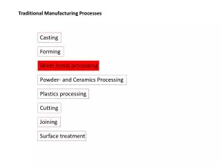
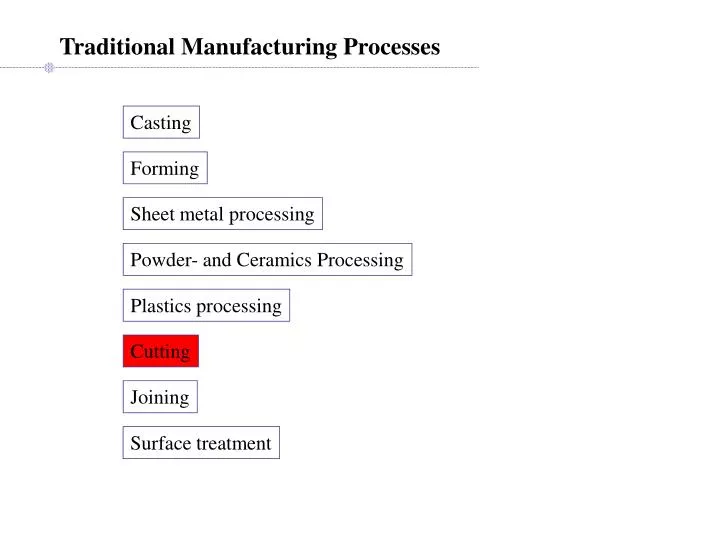
Traditional Manufacturing Processes. Casting. Forming. Sheet metal processing. Powder- and Ceramics Processing. Plastics processing. Cutting. Joining. Surface treatment. Cutting. Processes that involve removal of material from solid workpiece. Sawing Shaping (or planing),

E N D
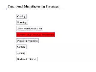
Traditional Manufacturing Processes Casting Forming Sheet metal processing Powder- and Ceramics Processing Plastics processing Cutting Joining Surface treatment
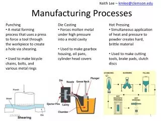
Cutting Processes that involve removal of material from solid workpiece Sawing Shaping (or planing), Broaching, drilling, Grinding, Turning Milling Important concept: PROCESS PLANNING Fixturing and Location Operations sequencing Setup planning Operations planning
Sawing A process to cut components, stock, etc. Process character: Precision: [very low,, very high]; MRR: low
Shaping A process to plane the surface of a workpiece (or to reduce part thickness Process character: High MRR, medium Surface finish, dimension control
Broaching Precise process for mass-production of complex geometry parts (complicated hole-shapes) Process character: High MRR, Very good surface, dimension control, Expensive
Drilling, Reaming, Boring Processes to make holes Process character: High MRR, Cheap, Medium-high surface, dimension control
Drilling basics - softer materials small point angle; hard, brittle material: larger point angle - Length/Diameter ratio is large gun-drilling (L/D ratio ~ 300) - Very small diameter holes (e.g. < 0.5 mm): can’t drill (why?) - F drilled hole > F drill: vibrations, misalignments, … - Tight dimension control: drill ream - Spade drills: large, deep holes - Coutersink/counterbore drills: multiple diameter hole screws/bolts heads
Tapping Processes to make threads in holes Process character: low MRR, Cheap, good surface, dimension control Automated tapping Manual tap and die set
Grinding, Abrasive Machining Processes to finish and smooth surfaces Process character: very low MRR, very high surface, dimension control 1. To improve the surface finish of a manufactured part (a) Injection molding die: milling manual grinding/electro-grinding. (b) Cylinders of engine: turning grinding honing lapping 2. To improve the dimensional tolerance of a manufactured part (a) ball-bearings: forging grinding [control: < 15 mm] (b) Knives: forged steel hardened grinding 3. To cut hard brittle materials (a) Semiconductor IC chips: slicing and dicing 4. To remove unwanted materials of a cutting process (a) Deburring parts made by drilling, milling
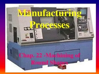
Turning Processes to cut cylindrical stock into revolved shapes Process character: high MRR, high surface, dimension control
[source: Kalpakjian & Schmid ] ] ] Milling Versatile process to cut arbitrary 3D shapes Process character: high MRR, high surface, dimension control
Common vertical milling cutters Flat Ballnose Bullnose
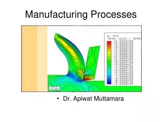
Process Analysis Fundamental understanding of the process improve, control, optimize Method: Observation modeling verification Every process must be analyzed; [we only look at orthogonal 1-pt cutting]
Modeling: Mechanism of cutting Old model: crack propagation Current model: shear
Tool wear: observations and models High stresses, High friction, High temp (1000C) tool damage Adhesion wear: fragments of the workpiece get welded to the tool surface at high temperatures; eventually, they break off, tearing small parts of the tool with them. Abrasion: hard particles, microscopic variations on the bottom surface of the chips rub against the tool surface Diffusion wear: at high temperatures, atoms from tool diffuse across to the chip; the rate of diffusion increases exponentially with temperature; this reduces the fracture strength of the crystals.
Tool wear, Tool failure, Tool life criteria • Catastrophic failure (e.g. tool is broken completely) • VB = 0.3 mm (uniform wear in Zone B), or VBmax = 0.6 mm (non-uniform flank wear) • KT = 0.06 + 0.3f, (where f = feed in mm/revolution).
Built-up edge (BUE) Deposition, work hardening of a thin layer of the workpiece material on the surface of the tool. BUE poor surface finish Likelihood of BUE decreases with (i) decrease in depth of cut, (ii) increase in rake angle, (iii) use of proper cutting fluid during machining.
Process modeling: empirical results Experimental chart showing relation of tool wear with f and V [source: Boothroyd]
Modeling: surface finish Relation of feed and surface finish
Analysis: Machining Economics How can we optimize the machining of a part ? Identify the objective, formulate a model, solve for optimality Typical objectives: maximum production rate, and/or minimum cost Are these objectives compatible (satisfied simultaneously) ? Formulating model: observations hypothesis theory model
Analysis: Machining Economics.. Formulating model: observations hypothesis theory model Observation: A given machine, tool, workpiece combination has finite max MRR Hypothesis: Total volume to cut is minimum Maximum production rate Model objective: Find minimum volume stock for a given part -- Near-net shape stocks (use casting, forging, …) -- Minimum enclosing volumes of 3D shapes Models: - minimum enclosing cylinder for a rotational part - minimum enclosing rectangular box for a milled part Solving: -- requires some knowledge of computational geometry
Analysis: Machining Economics.. Model objective: Find optimum operations plan and tools for a given part Example: or or ?? Model: Process Planning - Machining volume, tool selection, operations sequencing Solving: - in general, difficult to optimize
Analysis: process parameters optimization Model objective: Find optimum feed, cutting speed to [maximize MRR]/[minimize cost]/… Feed: Higher feed higher MRR Finish cutting: surface finish feed Given surface finish, we can find maximum allowed feed rate
Process parameters optimization: feed Rough cutting: MRR cutting speed, V MRR feed, f cannot increase V and f arbitrarily ↑V ↑ MRR; surface finish ≠ f(V); energy per unit volume MRR ≠ f(V) Tool temperature V, f; Friction wear V; Friction wear ≠ f For a given increase in MRR: ↑ V lower tool life than ↑ f Optimum feed: maximum allowed for tool [given machine power, tool strength]
Process parameters optimization: Speed Model objective: Given optimum feed, what is the optimum cutting speed provided upper limits, but not optimum Need a relation between tool life and cutting speed (other parameters being constant) Taylor’s model (empirically based): V tn = constant
Process parameters optimization: Speed One batch of large number, Nb, of identical parts Replace tool by a new one whenever it is worn Total non-productive time = Nbtl tl = time to (load the stock + position the tool + unload the part) Nb be the total number of parts in the batch. Total machining time =Nbtm tm = time to machine the part Total tool change time =Nttc tc = time to replace the worn tool with a new one Nt = total number tools used to machine the entire batch. Cost of each tool = Ct, Cost per unit time for machine and operator = M. Average cost per item:
Process parameters optimization: Speed Average cost per item: Let: total length of the tool path = L t = tool life Nt = (Nb tm)/t Nt / Nb = tm / t Taylor’s model Vtn = C’ t = C’ 1/n / V1/n = C/V1/n
Process parameters optimization: Speed Average cost per item:
Process parameters optimization: Speed Optimum speed (to minimize costs) Optimum speed (to minimize time) Average time to produce part:
Process parameters optimization: Speed Optimum speed (to minimize costs) Optimum speed (to minimize time) Average time to produce part: load/unload time tool change time machining time Substitute, differentiate, solve for V*
Process Planning The process plan specifies: operations tools, path plan and operation conditions setups sequences possible machine routings fixtures
Operation sequencing examples (Milling) big-hole step small hole or small holestep big-hole or … step hole or hole step
Traditional Manufacturing Processes Casting Forming Sheet metal processing Powder- and Ceramics Processing Plastics processing Cutting Joining Surface treatment
Joining Processes Types of Joints: 1. Joints that allow relative motion (kinematic joints) 2. Joints that disallow any relative motion (rigid joints) Uses of Joints: 1. To restrict some degrees of freedom of motion 2. If complex part shape is impossible/expensive to manufacture 3. To allow assembled product be disassembled for maintenance. 4. Transporting a disassembled product is sometimes easier/feasible
Joining Processes Fusion welding: joining metals by melting solidification Solid state welding: joining metals without melting Brazing: joining metals with a lower mp metal Soldering: joining metals with solder (very low mp) Gluing: joining with glue Mechanical joining: screws, rivets etc.
Flame: 3000C Fusion welding Oxy-acetylene welding Arc welding robotic manual arc: 30,000C Gas shielded arc welding MIG TIG Argon Al Ti, Mg, Thin sections
Fusion welding.. Deep, narrow welds Aerospace, medical, automobile body panels Plasma arc welding Faster than TIW, slower than Laser Nd:YAG and CO2 lasers, power ~ 100kW Laser beam welding Fast, high quality, deep, narrow welds deep, narrow welds, expensive Electron beam welding
Solid state welding Diffusion welds between very clean, smooth pieces of metal, at 0.3~0.5Tm Cold welding (roll bonding) coins, bimetal strips
Ultrasonic wire bonder 25mm Al wire on IC Chip Solid state welding.. Ultrasonic welding Medical, Packaging, IC chips, Toys Materials: metal, plastic - clean, fast, cheap
Resistance welding Welding metal strips: clamp together, heat by current Spot welding Seam welding
Brazing Tm of Filler material < Tm of the metals being joined Furnace brazing Torch brazing Common Filler materials: copper-alloys, e.g. bronze Common applications: pipe joint seals, ship-construction Soldering Tin + Lead alloy, very low Tm (~ 200C) Main application: electronic circuits