Download
1 / 20
210 likes | 307 Vues
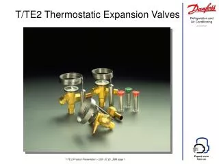
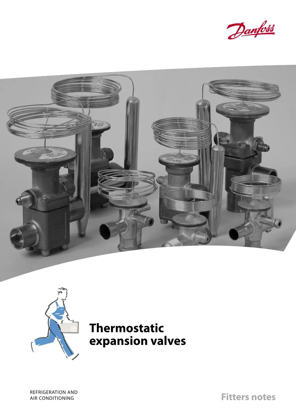
A thermostatic expansion valve is built up around a thermostatic element – separated from the valve body by a diaphragm. A capillary tube connects the element to a bulb and a valve body with valve seat and a spring. For more info, visit: http://www.danfoss.in<br>

E N D
Thermostatic expansion valves REFRIGERATION AND AIR CONDITIONING Fitters notes
Fitters notes Thermostatic expansion valves Contents Thermostatic expansion valves ............................................................................................................................3 Superheat .............................................................................................................................................................4 Subcooling ...........................................................................................................................................................4 External pressure equalization ......................................................................................................................4 Charges .........................................................................................................................................................................5 Universal charge .................................................................................................................................................6 MOP charge .........................................................................................................................................................6 MOP charge with ballast .................................................................................................................................6 Thermostatic expansion valve selection ...........................................................................................................7 Identification ...............................................................................................................................................................7 Installation ...................................................................................................................................................................9 Setting .........................................................................................................................................................................12 Orifice assembly replacement ............................................................................................................................13 Fault location ............................................................................................................................................................14 Danfoss product range ..........................................................................................................................................18 Page RZ1AH202 → DKRCC.PF.A00.A1.02 / 520H0337 2 © Danfoss A/S (RC-CMS/MWA), 03 - 2005
Fitters notes Thermostatic expansion valves A thermostatic expansion valve is built up around a thermostatic element (1) separated from the valve body by a diaphragm. A capillary tube connects the element to a bulb (2) and a valve body with valve seat (3) and a spring (4). A thermostatic expansion valve works like this: The function of a thermostatic expansion valve is determined by three fundamental pressures: P1: Bulb pressure which acts on the upper surface of the diaphragm, in the valve opening direction. P2: Evaporating pressure which acts on the underside of the diaphragm, in the valve closing direction. P3: Spring pressure which also acts on the underside of the diaphragm, in the valve closing direction. When the expansion valve regulates, balance is created between bulb pressure on one side of the diaphragm and evaporating pressure plus spring force on the other side. The spring is used to set superheat. Ad0-0001 © Danfoss A/S (RC-CMS/MWA), 03 - 2005RZ1AH202 → DKRCC.PF.A00.A1.02 / 520H0337 3
Fitters notes Thermostatic expansion valves Superheat Superheat is measured at the point where the bulb is located on the suction line and is the difference between the temperature at the bulb and the evaporating pressure/evapora- ting temperature at the same point. Superheat is measured in Kelvin (K) or °C and is used as a signal to regulate liquid injection through the expansion valve. Ad0-0012 Subcooling Subcooling is defined as the difference between condensing pressure/temperature and liquid temperature at the expansion valve inlet. Subcooling is measured in Kelvin (K) or °C. Subcooling of the refrigerant is necessary to avoid vapour bubbles in the refrigerant ahead of the expansion valve. Vapour bubbles in the refrigerant reduce capacity in the expansion valve and thereby reduce liquid supply to the evaporator. Subcooling of 4-5K is adequate in most cases. Ad0-0015 External pressure equalization Expansion valves with external pressure equali- zation must always be used if liquid distributors are installed. Typically, the use of distributors gives a pressure drop of 1 bar across distributor and distribution tubes. Expansion valves with external pressure equali- zation should always be used in refrigeration systems with small compact evaporators, e.g. plate heat exchangers, where normally the pressure drop will be greater than pressure corresponding to 2K. Ad0-0016 RZ1AH202 → DKRCC.PF.A00.A1.02 / 520H0337 4 © Danfoss A/S (RC-CMS/MWA), 03 - 2005
Fitters notes Thermostatic expansion valves Charges Thermostatic expansion valves can contain one of three different types of charge: 1. Universal charge 2. MOP charge 3. MOP charge with ballast, standard for Danfoss expansion valves with MOP. Expansion valves with Universal charge are used in most refrigeration systems where there is no pressure limitation requirement and where the bulb can be located warmer than the element or at high evaporating temperature/evaporating pressure. Ad0-0017 Expansion valves with MOP charge are typically used on factory-made units where suction pressure limitation on starting is required, e.g. in the transport sector and in air conditioning systems. All expansion valves with MOP have a very small charge in the bulb. This means that the valve or the element must be located warmer than the bulb. If it is not, charge can migrate from the bulb to the element and prevent the expansion valve from functioning. Ad0-0018 Expansion valves with MOP ballast charges are used mainly in refrigeration systems with “high- dynamic” evaporators, e.g. in air conditioning systems and plate heat exchangers with high heat transfer. With MOP ballast charge, up to 2 - 4K (°C) less superheat can be obtained than with other types of charge. Ad0-0021 © Danfoss A/S (RC-CMS/MWA), 03 - 2005RZ1AH202 → DKRCC.PF.A00.A1.02 / 520H0337 5
Fitters notes Thermostatic expansion valves Universal charge means that there is liquid charge in the bulb. The amount of charge is so large that charge remains in the bulb irrespective of whether the element is colder or warmer than the bulb. Ad0-0017 MOP charge means limited liquid charge in the bulb. “MOP” stands for Maximum Operating Pressure and is the highest suction pressure/ evaporating pressure permissible in the evaporator/suction line. The charge will have evaporated when the temperature reaches the MOP point. Gradually, as the suction pressure rises, the expansion valve begins to close at approx. 0.3/0.4 bar below the MOP point. It becomes completely closed when the suction pressure is the same as the MOP point. Ad0-0018 MOP is often called “Motor Overload Protec- tion”. MOP charge with ballast The bulb in a thermostatic expansion valve contains a material of high porosity and large surface area in relation to weight. MOP charge with ballast has a damping effect on expansion valve regulation. The valve opens slowly as bulb temperature rises and closes quickly as bulb temperature fails. Ad0-0021 RZ1AH202 → DKRCC.PF.A00.A1.02 / 520H0337 6 © Danfoss A/S (RC-CMS/MWA), 03 - 2005
Fitters notes Thermostatic expansion valves Thermostatic expansion valve selection The thermostatic expansion valve can be selec- ted when the following are known: • Refrigerant • Evaporator capacity • Evaporating pressure • Condensing pressure • Subcooling • Pressure drop across valve • Internal or external pressure equalization Identification The thermostatic element is fitted with a label (on top of the diaphragm). The code refers to the refrigerant for which the valve is designed: X = R 22 Z = R 407C N = R 134a L = R 410A S = R 404A/ R507 The label gives valve type, evaporating tem- perature range, MOP point, refrigerant, and max. test pressure, PB/MWP. PS With TE 20 and TE 55 the rated capacity is stamped on a band label fastened to the valve. Ad0-0019 Note! From Sept. 1997 the coloured label on the element of T/TE2 thermostatic expansion valves has been replaced by a laser engraved inscription © Danfoss A/S (RC-CMS/MWA), 03 - 2005RZ1AH202 → DKRCC.PF.A00.A1.02 / 520H0337 7
Fitters notes Thermostatic expansion valves The orifice assembly for T/TE 2 is marked with the orifice size (e.g. 06) and week stamp + last number in the year (e.g. 279). The orifice assembly number is also given on the lid of its plastic container. Ad0-0023 On TE 5 and TE 12 the upper stamp (TE 12) indicates for which valve type the orifice can be used. The lower stamp (01) is the orifice size. On TE 20 and TE 55 the lower stamp (50/35 TR N/B) indicates the rated capacity in the two evaporating temperature ranges N and B, and the refrigerant. (50/35 TR = 175 kW in range N and 123 kW in range B). The upper stamp (TEX 55) refers to the valve type for which the assembly can be used. Ad0-0020 RZ1AH202 → DKRCC.PF.A00.A1.02 / 520H0337 8 © Danfoss A/S (RC-CMS/MWA), 03 - 2005
Fitters notes Thermostatic expansion valves Installation The expansion valve must be installed in the liquid line, ahead of the evaporator, with its bulb fastened to the suction line as close to the evaporator as possible. If there is external pressure equalization, the equalizing line must be connected to the suction line immediately after the bulb. Ad0-0002 The bulb is best mounted on a horizontal suction line tube and in a position corresponding to between 1 o’clock and 4 o’clock. Location depends on the outside diameter of the tube. Note: The bulb must never be located at the bottom of the suction line due to the possibility of oil laying in the bottom of the pipe causing false signals. Ad0-0003 © Danfoss A/S (RC-CMS/MWA), 03 - 2005RZ1AH202 → DKRCC.PF.A00.A1.02 / 520H0337 9
Fitters notes Thermostatic expansion valves The bulb must be able to sense the temperature of the superheated suction vapour and must therefore not be located in a position that will expose it to extraneous heat/cold. If the bulb is exposed to a warm air current, insulation of the bulb is recommended. Ad0-0004 The bulb must not be installed after a heat exchanger because in this position it will give false signals to the expansion valve. Ad0-0005 The bulb must not be installed close to com- ponents of large mass as this also will give rise to false signals to the expansion valve Ad0-0006 RZ1AH202 → DKRCC.PF.A00.A1.02 / 520H0337 10 © Danfoss A/S (RC-CMS/MWA), 03 - 2005
Fitters notes Thermostatic expansion valves As previously mentioned, the bulb must be installed to the horizontal part of the suction line immediately after the evaporator. It must not be installed to a collection tube or a riser after an oil pocket. Ad0-0007 The expansion valve bulb must always be installed ahead of any liquid lock. Ad0-0008 © Danfoss A/S (RC-CMS/MWA), 03 - 2005RZ1AH202 → DKRCC.PF.A00.A1.02 / 520H0337 11
Fitters notes Thermostatic expansion valves Setting The expansion valve is supplied with a factory setting suitable for most applications. If necessary, readjustment can be made using the setting spindle on the valve. Turning the spindle clockwise increases the expansion valve superheat and turning it counterclock-wise reduces it. For T /TE 2, one turn of the spindle produces a change of approx. 4K (°C) in the superheat at 0°C evaporating temperature. Ad0-0009 For TE 5 and following sizes, one turn of the spindle produces a change of approx. 0.5K in the superheat at 0°C evaporating tempera- ture. For TUA and TUB, one turn of the spindle produces a change of approx. 3K in the super- heat at 0°C evaporating temperature. Ad0-0010 Hunting in the evaporator can be eliminated by the following procedure: Increase the superheat by turning the expansion valve setting spindle well to the right (clockwise) so that hunting stops. Then turn the setting spindle in counter-clockwise steps so that hunting again occurs. From this position, turn the spindle about once clockwise (but only 1/4 turn for T /TE 2 valves). On this setting the refrigeration system will not hunt and the evaporator is fully utilized. A variation of ±0.5°C in superheat is not regarded as hunting. Ad0-0011 RZ1AH202 → DKRCC.PF.A00.A1.02 / 520H0337 12 © Danfoss A/S (RC-CMS/MWA), 03 - 2005
Fitters notes Thermostatic expansion valves If the superheat in the evaporator is too high, the reason might be an inadequate supply of liquid refrigerant. The superheat can be reduced by turning the expansion valve setting spindle counterclockwise in steps until hunting is observed. From this setting, the spindle must be turned about once clockwise (but only 1/4 turn for T/TE 2). This setting fully utilizes the evaporator. A variation of ±0.5°C in superheat is not regarded as hunting. Ad0-0013 Orifice assembly replacement If the evaporator continues to hunt, regardless of the superheat setting, the valve capacity might be too high and the orifice assembly, or the valve, needs replacing with a smaller one. If the evaporator superheat is too high the valve capacity is too low and the orifice assembly must be replaced with a larger one. TE, T2, TUA, TCAE valves are supplied with an interchangeable orifice. Ad0-0014 © Danfoss A/S (RC-CMS/MWA), 03 - 2005RZ1AH202 → DKRCC.PF.A00.A1.02 / 520H0337 13
Fitters notes Thermostatic expansion valves Fault location Symptom Room temperature too high. Possible cause Pressure drop across evaporator too high. Remedy Replace expansion valve with valve having external pressure equalization. Reset superheat on expansion valve if necessary. Lack of subcooling ahead of expansion valve. Check refrigerant subcooling ahead of expansion valve. Establish greater subcooling. Pressure drop across expansion valve less than the pressure drop the valve is sized for. Check pressure drop across expansion valve. Try replacement with larger orifice assembly and/or valve. Reset superheat on expansion valve if necessary. Check bulb location. Locate bulb away from large valves, flanges, etc. Bulb located after a heat exchanger or too close to large valves, flanges, etc. Expansion valve blocked with ice, wax or other impurities. Clean ice, wax or other impurities from the valve. Check sight glass for colour change (green means too much moisture). Replace filter drier if fitted. Check oil in the refrigeration system. Has the oil been changed or replenished? Has the compressor been replaced? Clean the filter. Check refrigeration system capacity and compare with expansion valve capacity. Replace with larger valve or orifice. Reset superheat on expansion valve. Check expansion valve for loss of charge. Replace expansion valve. Reset superheat on expansion valve. Expansion valve too small. Charge lost from expansion valve. Charge migration in expansion valve. Check whether expansion valve charge is correct. Identify and remove cause of charge migration. Reset superheat on expansion valve if necessary. Ensure that bulb is secured on suction line. Insulate bulb if necessary. De-ice evaporator if necessary. Room temperature too high. Expansion valve bulb not in good contact with suction line. Evaporator completely or partly iced up. Refrigeration system hunts. Expansion valve superheat set at too small a value. Expansion valve capacity too high. Reset superheat on expansion valve. Replace expansion valve or orifice with smaller size. Reset super heat on expan- sion valve if necessary. Check bulb location. Locate bulb so that it receives a reliable signal. Ensure that bulb is secured on suction line. Set super- heat on expansion valve if necessary. Refrigeration system hunts at too high a room temperature. Expansion valve bulb location inappropriate, e.g. on collection tube, riser after oil lock, or near large valves, flanges or similar. RZ1AH202 → DKRCC.PF.A00.A1.02 / 520H0337 14 © Danfoss A/S (RC-CMS/MWA), 03 - 2005
Fitters notes Thermostatic expansion valves Symptom Suction pressure too high. Possible cause Liquid flow Expansion valve too large. Expansion valve setting incorrect. Remedy Check refrigeration system capacity and compare with expansion valve capacity. Replace with larger valve or orifice. Reset superheat on expansion valve. Check expansion valve for loss of charge. Replace expansion valve. Reset superheat on expansion valve. Charge lost from expansion valve. Charge migration in expansion valve. Increase superheat on expansion valve. Check expansion valve capacity in relation to evaporator duty. Replace expansion valve or orifice with smaller size. Reset superheat on expansion valve if necessary. Replace expansion valve with valve having external pressure equalization. Reset superheat on expansion valve if necessary. Check refrigerant subcooling ahead of expansion valve. Establish greater subcooling. Check superheat. Reset superheat on expansion valve. Check pressure drop across expansion valve. Replace with larger orifice assembly and/or valve if necessary. Check bulb location. Insulate bulb if necessary. Locate bulb away from large valves, flanges, etc. Check refrigeration system capacity and compare with expansion valve capacity. Replace with larger valve or orifice. Reset superheat on expansion valve. Clean ice, wax and other impurities from valve. Check sight glass for colour change (yellow means too much moisture). Re- place filter drier if fitted. Check oil in the refrigeration system. Has the oil been changed or replenished? Has the compressor been replaced? Clean the filter. Check expansion valve for loss of charge. Replace expansion valve. Reset superheat on expansion valve. Check charge in expansion valve. Reset superheat on expansion valve if necessary. De-ice evaporator if necessary. Suction pressure too low. Pressure drop across evaporator too high. Lack of subcooling ahead of expansion valve. Evaporator superheat too high. Pressure drop across expansion valve less than pressure drop valve is sized for. Bulb located too cold, e.g. in cold air flow or near large valves, flanges, etc. Expansion valve too small. Expansion valve blocked with ice, wax or other impurities. Charge lost from expansion valve. Charge migration in expansion valve. Evaporator wholly or partly iced up. © Danfoss A/S (RC-CMS/MWA), 03 - 2005RZ1AH202 → DKRCC.PF.A00.A1.02 / 520H0337 15
Fitters notes Thermostatic expansion valves Symptom Liquid hammer in compressor. Possible cause Expansion valve capacity too large. Remedy Replace expansion valve or orifice with smaller size. Reset superheat on expansion valve if necessary. Increase superheat on expansion valve. Superheat on expansion valve set too low. Expansion valve bulb not in good contact with suction line. Bulb located too warm or near large valves, flanges, etc. Ensure that bulb is secured on suction line. Insulate bulb if necessary. Check bulb location on suction line. Move bulb to better position. RZ1AH202 → DKRCC.PF.A00.A1.02 / 520H0337 16 © Danfoss A/S (RC-CMS/MWA), 03 - 2005
Fitters notes Thermostatic expansion valves Danfoss product range Thermostatic expansion valves Danfoss offers a comprehensive range of thermostatic expansion valves with capacities from 0.5 to 1090 kW (R 22). T/TE 2 valves have a brass housing and flare/ flare or solder/flare connections. Rated capacity: 0.5 - 15.5 kW (R 22). TDE valves have a brass housing and copper solder connections. Rated capacity: 10.5 - 140 kW (R 22) The valves are supplied with a fixed orifice and adjustable superheat. TUA, TUB, TUC valves have a stainless steel housing and stainless steel/copper bimetal solder connections. TE 5 - TE 55 valves have a brass housing. The valves are supplied as a part programme consisting of valve housing, orifice and thermo- static element. Rated capacity: 0.6 - 16 kW (R 22). The valves can be supplied with or without external pressure equalization. - TUA has an interchangeable orifice assembly and adjustable superheat. - TUB has a fixed orifice and adjustable superheat. - TUC has a fixed orifice and factory set superheat. The valve housing is available in a straightway or angleway version with solder, flare and flange connections. Rated capacity: 19.7 - 356 kW (R22). The valves are supplied with external pressure equalization. TUB and TUC are primarily for OEM customers. All TUB and TUC valves can be replaced by TUA valves. PHT 85 - 300 valves are supplied as a part programme consisting of valve housing, flanges, orifice and thermostatic element. TCAE, TCBE, TCCE valves have a stainless steel housing and stainless steel/copper bimetal solder connections. Rated capacity: 105 - 1890 kW (R 22). Rated capacity: 17.5 - 26.5 kW (R 22). For further information consult the internet or the catalogue material. The valves are designed as the TU valves but with a higher capacity. The valves are supplied with external pressure equalization. TRE valves have a brass housing and stainless steel/copper bimetal connections. Rated capacity: 28 - 245 kW (R 22). The valves are supplied with a fixed orifice and adjustable superheat. © Danfoss A/S (RC-CMS/MWA), 03 - 2005RZ1AH202 → DKRCC.PF.A00.A1.02 / 520H0337 17
The Danfoss product range for the refrigeration and air conditioning industry Appliance Controls General temperature controls for the home appliance industry. The product range comprises CFC-free electromechanical and electronic thermostats for refrigerators and freezers produced to customer specifications as well as service thermostats for all refrigeration and freezing appliances. Refrigeration and air conditioning controls A comprehensive and highly reputed range of self-acting valves, electronic valves and regulators as well as system protectors and line components for the refrigeration and air conditioning market. These products include thermostatic expansion valves, solenoid valves, thermostat and pressure controls, modulation pressure regulators, filter driers, shut-off valves, sight glasses, check valves, non-return valves and water valves. Decentralised electronic systems for full regulation and control of refrigeration applications are also developed and produced at Danfoss. Commercial Compressors Large hermetic reciprocating and scroll com- pressor technologies for commercial air conditioning and refrigeration. The compressors and condensing units are used in a large array of applications in both businesses. This ranges from water chillers, large packaged air conditioners as well as medium and low temperature refrigeration systems for food storage and processing. Industrial Controls Products and customer specific solutions for industrial monitoring and controls systems based on the principles of pressure and temperature measurement, electrical power and fluid control. Products include a wide range of automatic controls for process control and regulation such as contactors and motor starters, electrically, pneumatically and temperature activated valves as well as temperature and pressure transmitters and switches. Danfoss Compressors Hermetic compressors and fan-cooled con- densing units for refrigerators, freezers and light commercial applications such as bottle coolers and display counters. Danfoss also produces compressors for heating pump systems as well as 12 and 24 volt compressors for refrigerators and freezers used in mobile applications and solar power. The division has a leading position within energy utilisation, noise filtering and know-how about environment-friendly compressors. RZ1AH202 → DKRCC.PF.A00.A1.02 / 520H0337 © Danfoss A/S (RC-CMS/MWA), 03 - 2005