Download
1 / 65
670 likes | 948 Vues
TAILINGS BASIN RECLAMATION ATLANTIC CITY IRON MINE, WYOMING. J. J. Gusek P.E., Linkan Engineering, Golden, CO & B.K. Schladweiler, BKS Environmental, Gillette, WY. WYOMING AML PROJECT 9A-II. Site Location. Southern end of the Wind River Mountains

E N D
TAILINGS BASIN RECLAMATIONATLANTIC CITY IRON MINE, WYOMING J. J. Gusek P.E., Linkan Engineering, Golden, CO & B.K. Schladweiler, BKS Environmental, Gillette, WY WYOMING AML PROJECT 9A-II
Site Location • Southern end of the Wind River Mountains • 35 mi south of Lander WY on South Pass (WY Highway 28)
SITE HISTORY • Iron resource recognized during Cold War • This mine and the Sharon Steel Mill in SLC were located out of range of ICBMs at the time. • US Steel operated mine 1962 to 1983 • Salvage operator acquired property in about 1985 for railroad rails but later sold • WY AML assumed some of reclamation responsibility in late 1980’s
Site Environment • Site elevation – 8,100 ft (2,470 m) • Strong winds • Short growing season • Semi-arid/high altitude climate
SITE SPECIFIC PROBLEMSPrior to Reclamation • A tailings basin cap installed in 1985 was being eroded by uncontrolled ground water seeps • Wind-blown dust from the tailings basin was causing zero visibility on adjacent state highway to the south
Challenges • Site conditions described previously • On-going drought during construction and reclamation • 8-year drought • Most intense period August 2002 • No topsoil originally salvaged/source of borrow topsoil
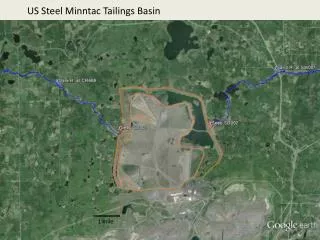
SITE LAYOUT Relocated HWY 28 (2003?)
Seeps eroding vegetative cover soil SEEPAGE FROM PIT LAKE
Mill and Tailings Basin 1994 Partly Revegetated Seeps Exposed Tailings Tailings Pond discharging through decant tower
WY AML’s Responsibilities • Reclaim lands not covered by owner obligations • Tailings Basin Reclamation • Portions of Waste Rock Dumps • Railroad Bridge Abutments • Railroad Fill Removal/Breaching
INITIAL PROJECT GOALS • Provide a stable reclaimed surface to prevent blowing dust and develop habitat for wildlife and cattle grazing • Preserve or improve the stormwater protection the mine pit and tailings basin provided to downstream communities, especially during construction
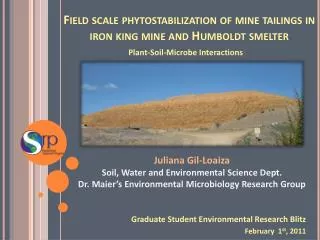
PRE-DESIGN INVESTIGATIONS • Geotechnical - 2 tailings dams (North and South) • Site geochemistry • Surface water hydrology • Feasibility of compost use • Soils and revegetation • Threatened & endangered species
Reclamation Plan Specifics • Rock wall snow fences substituted for vertical slat snow fences • Fertil Fiber/Kiwi-Power amendments with nearby White River overburden substituted for organic compost or imported topsoil • Based on historical research of taconite tailings • WRF low fertility but no chemical limitations (neutral pH; As <2 mg/kg) • Broadcast seed • Plant adapted species @ 40 kg/ha PLS (35-36 lbs/ac)
SOIL AMENDMENTS • (DRY) Fertil Fibers/Biosol applied in two doses @2.2 t/ha (1.0 st/ac) with dry inorganic fertilizer supplement • (WET) Kiwi Power bacterial inoculum applied at 47 liters/ha (5 gallons/acre) applied with “crop duster” airplane.
Fertilizer • Diammonium phosphate fertilizer 250 lb/acre • 45 lbs elemental N • 115 lbs elemental P • Potash 36 lb/acre • 30 lbs elemental K
Mulching • Other than hydroseeded/hydromulched areas, no mulching was used
Seed Mix – Drill Rate • CritanaThickspike 3.0 PLS/ac • Rosana Western 3.0 PLS/ac • SecarBluebunch 3.0 PLS/ac • Bromar Mountain Brome 4.0 PLS/ac • Trailhead Basin Wildrye 2.0 PLS/ac • Joseph Idaho Fescue 2.0 PLS/ac • Appar Blue Flax 0.5 PLS/ac • EskiSanfoin 2.0 PLS/ac • Mountain Big Sagebrush 1.0 PLS/ac • TOTAL 17.5 PLS/ac
Fencing • Cattle grazing excluded for two growing seasons • Wildlife grazing could not be economically excluded
CONSTRUCTION SCHEDULE • Dec, 1996 - Winter startup/regrading of initial tailings basin • Nov, 1997 - Winter weather suspends revegetation work • Spring, 1998 – revegetation work complete, regrade other sites in project
Tree Planting • Conducted in 2001 • Two tree species in wind shadows of rock berms and rock boulder snow fences (15,000 trees) • Used 2’ x 2’ black matting • Lodgepole and limber pines – seeds harvested from forest within 500 feet of the mine and grown in containers in a CO nursery • Installed browse protection sleeves
Reclamation Project Areas/Phases • Tailings Storage Facility (TSF) (impoundment) including tree planting – Phase 1 • RR bridge abutment removal – Phase 1A • Waste rock dumps – Phase 2 • Railroad fill breaching – Phase 3
SITE LAYOUT Relocated HWY 28 (2003?)
Challenges • New spillway 10 ft lower than the normal Iron Lake level. • Constructing the spillway without creating a flood was a challenge. • However, as excavation occurred closer to the Lake, the “seepage” encountered increased so that the lake level dropped in a controlled fashion. • Seep flow on the north end of the TSF managed with French Drains that daylighted at the tailings pond shoreline
Iron Lake to Tailings Pond Spillway Iron Lake New Spillway Iron Lake water level 10 ft. lower to eliminate seeps) Tailings Pond
Closure of Lower Diversion Canal/Old Spillway Lower Diversion Canal Alignment Iron Lake French Drains Old Spillway Tailings Pond Tailings Dam
New Tailings Basin Spillway Iron Lake French Drains New Spillway Tailings Pond Tailings Dam
Tailings Basin Post-Construction Iron Lake Spillway Tailings Pond Rock Boulder Snow Fence Buried French Drains in this area
Tailings Basin + 2 yrs. Iron Lake Spillway Tailings Pond Buried French Drains in this area
Tree Planting Assessment on Tailings Basin • Used Google Earth Imagery to count trees around 36 rock boulder snow fences • Used to determine tree survival rate • Lowest survival rate at a rock boulder snow fence was 11% • Highest survival rate at a rock boulder snow fence was 80% • Average survival rate at a rock boulder snow fence was 41%
Overall Statistics What happend?
Big Sagebrush – NE of tailings basin • NE of tailings basin • Simultaneously broadcasted shrub seed within drill seeded grasses
Reclamation Project Areas/Phases • Tailings Storage Facility (TSF) (impoundment) – Phase 1 • RR bridge abutment removal – Phase 1A • Waste rock dumps – Phase 2 • Railroad fill breaching – Phase 3
Hazards • Long considered a “choke point” on a long downhill stretch of highway that, under wintery conditions, could have resulted in a fatality if a vehicle hit the abutments. • The abutments were also considered a hazard to snowmobilers who routinely used the railroad right of way. • WY AML elected to have them removed.
Photos courtesy of Tim Richmond, WY AML (retired) Bridge Abutment Removal Phase 1A
Reclamation Project Areas/Phases • Tailings Storage Facility (TSF) (impoundment) – Phase 1 • RR bridge abutment removal – Phase 1A • Waste rock dumps – Phase 2 • Railroad fill breaching – Phase 3
SITE LAYOUT Relocated HWY 28 (2003?)
Considerations • While the un-reclaimed waste rock areas presented no physical hazards, their reclamation was within AML’s mission statement. • Some of the advancements on the tailings project were transferred to the waste rock projects (e.g., rock snow fences)
Waste Rock Reclamation (Phase 2) Ripping and Final Shaping
Atlantic City: Phase 2 (con’t) Placing Cover Materials on Waste Dumps
Atlantic City: Phase 2 (con’t) Incorporating Soil Amendments and Fertilizers
Pitted Surface on Slopes • Improves soils moisture capture and retention • Reduces wind erosion and abrasion of young seedlings
Atlantic City: Phase 2 (con’t) Hydroseeding
Reclamation Project Areas/Phases • Tailings Storage Facility (TSF) (impoundment) – Phase 1 • RR bridge abutment removal – Phase 1A • Waste rock dumps – Phase 2 • Railroad fill breaching – Phase 3